This thread has been locked.

If you have a related question, please click the "Ask a related question" button in the top right corner. The newly created question will be automatically linked to this question.

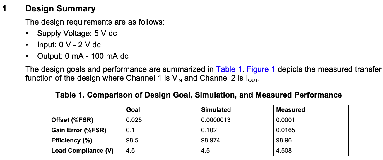
OPA445: slau501 - Possible to modify Voltage to current converter design for bi-phasic input voltage?

Part Number: OPA445
Other Parts Discussed in Thread: XTR111, OPA564, OPA454, OPA552, OPA192, OPA551

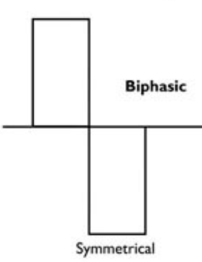
I wish to apply this design; I'm generating a -1.6 ~ 1.6V bi-phasic square pulse signal using an Arduino DUE's DAC by adding a highpass filter.

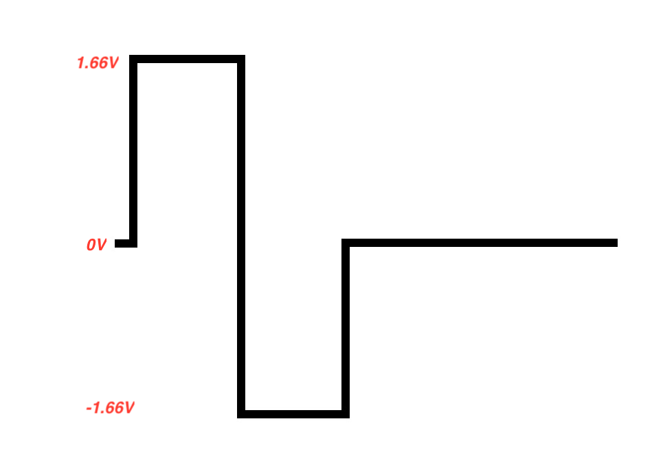
The signal will be reaching 1.6V or -1.6V for a short duration and the rest will be 0V during the period.

This signal's amp can be changed to increase or decrease the output current later on. The signal's frequency will be ranging to 50 ~ 8,000 Hz.

- Using the formula, I want no currents to flow when my input voltage signal is 0V.

- I want to generate a negative current using the above bi-phasic voltage pulse

- I will add a load resistor ranging from 500 ~ 1,000,000 Ω.

- My desired current amount is 100mA regardless of the load resistor.

- I have a power supply that can support up to 30 V.

So I want to change the Op Amp to TI's OPA445APG4.

How should I change the design in slau501 to achieve my requirements?

Suggesting a different TI's Op Amp, transistors, etc are welcomed and I will order them to implement it.

Or, if it is better to use TI's Voltage-to-Current converter ICs like this,

tell me, please.

-Thanks for your help

  • Hi David,

    have you considered using the Improved Howland Current Pump for your project?

    https://e2e.ti.com/support/amplifiers/f/14/t/673984

    https://e2e.ti.com/support/amplifiers/f/14/t/699812

    Kai

  • Hi, Kai. I never heard of it.
    www.ti.com/.../snoa474a.pdf

    Allow me to read about this.

    Also, your link is abbreviated so I cannot take a look.

    Can you provide the link and give me some explanation related to Howland Current Pump and its advantages?

    -Thanks!
  • Hi David,

    type the 6 digit number at the end of the link address into the search box...

    Kai
  • Hi David,

    Your comments:

    This signal's amp can be changed to increase or decrease the output current later on. The signal's frequency will be ranging to 50 ~ 8,000 Hz.

    - Using the formula, I want no currents to flow when my input voltage signal is 0V.

    Any operational amplifier will have input bias current; therefore, the current in the input loop will not be zero. The best you can do is to use an op amp that has very low input bias current.

    - I want to generate a negative current using the above bi-phasic voltage pulse

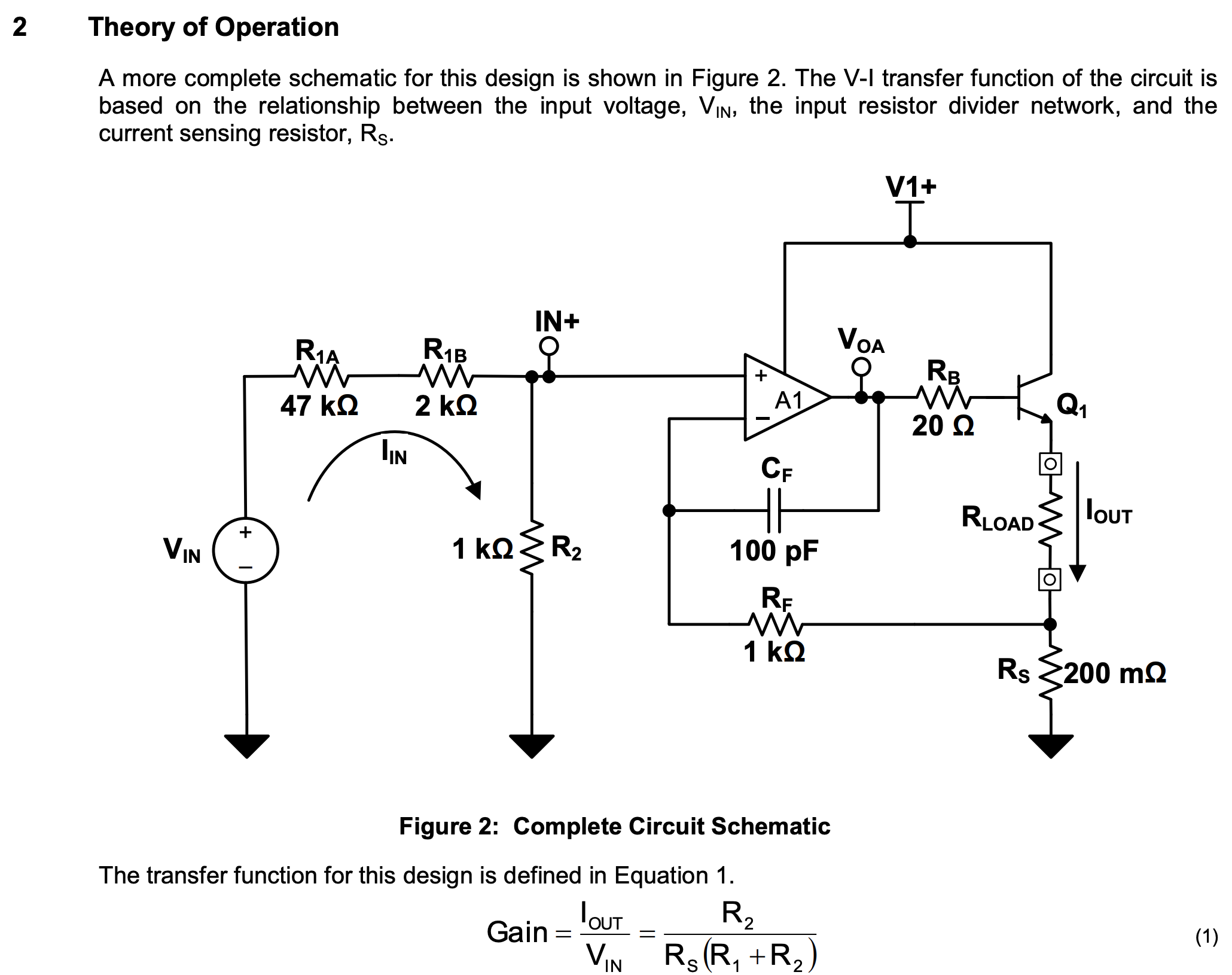
    Does this mean that you only want an output current when the input voltage is negative? By negative current convention would dictate the Iout current would be in the direction as shown in the Figure 2 diagram. Also see the Improved Howland Current Pump that Kai references. I can be set up for ac bidirectional current through a load.

    - I will add a load resistor ranging from 500 ~ 1,000,000 Ω.

    Well, you can do that but the current source circuit isn't going to work as you want. You mention below an output current of 100 mA. If you apply Ohm's Law to a 500 ~ 1,000,000 Ω resistance range that equates to an output voltage range of 50 V to 100,000 V. You need to establish a reasonable output voltage compliance range that the circuit is capable of providing.

    - My desired current amount is 100mA regardless of the load resistor.

    See my answer to your 500 ~ 1,000,000 Ω application.

    - I have a power supply that can support up to 30 V.

    So I want to change the Op Amp to TI's OPA445APG4.

    The OPA445APG4 is specified for +/-15 mA output current, and it won't be able to provide 100 mA. The OPA454 might work, but for 100 mA output current you will really have to consider the thermal constraints of the device. If you can use a +24 V supply, the OPA564 will easily provide the 100 mA output and can dissipate more power. It is a CMOS power op amp and the input current is typically 10 pA at room temperature.

    Regards, Thomas
    Precision Amplifiers Applications Engineering
  • Thomas Kuehl said:
    Also see the Improved Howland Current Pump that Kai references. I can be set up for ac bidirectional current through a load.

    If you apply Ohm's Law to a 500 ~ 1,000,000 Ω resistance range that equates to an output voltage range of 50 V to 100,000 V. You need to establish a reasonable output voltage compliance range that the circuit is capable of providing.

    - My desired current amount is 100mA regardless of the load resistor.

    Thanks, Tomas. I created the Howland Current Pump circuit on the breadboard using ADA4000-2ARZ, which can supply +- 18V.

    Just like you’ve mentioned, if I add a big load like 2k Ohm,  the Op Amp output of the current pump becomes saturated, only providing 16.5 V output.

    So the real current supplied is smaller than I wanted. I tested this on room temperature and I will use this system on room temperature as well.

    BTW, the maximum current I desire is 100mA; I will control the current using the Arduino”s DAC voltage level.

    I’m hooking up a load that has a varying impedance over time with the aforementioned range.

    Thomas Kuehl said:
    Any operational amplifier will have input bias current; therefore, the current in the input loop will not be zero.

    Thomas Kuehl said:

    - I want to generate a negative current using the above bi-phasic voltage pulse

    Does this mean that you only want an output current when the input voltage is negative?

    Both negative and positive + I want to draw 0 A of currents (as possible) when the input signal's voltage is near 0V;


    When the DAC gives 0V or 3.3V (this will go through an HFP and become -1.6V and 1.6V), I want to create the current output.

    Most of the time, the signal will show 0V. When the DAC signal shows the 1.6V or -1.6V pulse, I want to create a current output.

    The duration of the pulse is short (50 micro seconds) and the rest 0.01 seconds are 0 V.

    Thomas Kuehl said:
    By negative current convention would dictate the Iout current would be in the direction as shown in the Figure 2 diagram.

    I thought the current direction for Figure 2 is the case when the voltage is positive, isn’t it?

    Due to my situation, I think the Improved Howland Current Pump may not be suitable for me.

    So I was thinking of using the TI’s slau501 (Op Amp + NPN) / slau502 (Op Amps + MOSFET) / Wilson current mirror using MOSFET / or something like XTR111 Precision Voltage-to-Current Converter


    The negative voltage must be converted to a current output.

    What are your recommendations? Hope to hear your feedback, please.

  • Hello David,

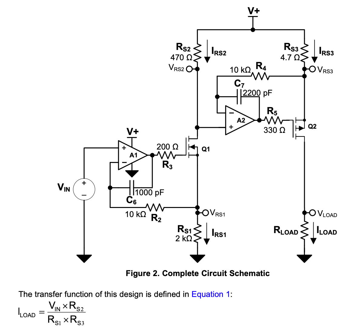
    You mentioned that you want the current to be sourced to the load when the input voltage is negative. The circuit in Figure 2 only sources current when VIN has a positive polarity. If you invert the voltage applied to VIN, then the output would source the current at time that corresponds with the -1.66 V input level. A benefit of this circuit is the output current will shut off when the input, before the inverter, goes to positive 1.66 V. The non-inverting input of A1 would need a few kilohm series resistor added to limit the input current when the input is driven below ground.

    You can see a TINA simulation image of this circuit in action with plus +1.66 V applies and 100 mA being sourced out the output.

    A less involved current source circuit based on the one that you originally had shown can be realized with one OPA454 high-voltage op amp. It is shown below. Note that the load RL isn't connected to ground but is connected between the OPA454 output and the sense resistor which connects to ground. That may not be usable in your application. Also, the current source output current is bidirectional. It will source the 100 mA current when the input is -1.66 V, and sink current when the input is +1.66 V.

    Regards, Thomas

    Precision Amplifiers Applications Engineering

  • I deeply appreciate your help, Thomas.

    Thomas Kuehl said:
    Note that the load RL isn't connected to ground but is connected between the OPA454 output and the sense resistor which connects to ground.

    Thomas Kuehl said:
    That may not be usable in your application.

    One thing I forgot to mention; my load is connected to GND and the current converter. However, if there's a better solution for this, the other side of the load doesn't need to be connected to GND.

    Thomas Kuehl said:
    The non-inverting input of A1 would need a few kilohm series resistor added to limit the input current when the input is driven below ground.

    Is A1 the first stage amp? Also, is the first schematic feasible for my situation? I think I haven't understood your point, yet. Since I don't see the negative power supply in the first case, I'm not sure whether I can use it or not.

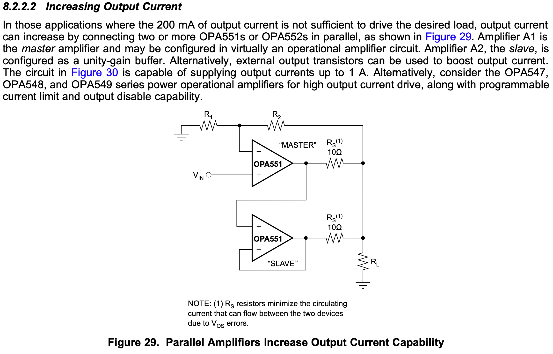
    Or how about adding "parallel Amps"? I saw this from the opa552 datasheet. Could this solve my concerns?

  • Hi David,

    you still haven't answered Thomas' question: Why do you want to drive a current of 100mA through a load of 1M? This would mean a voltage drop of 100kV!

    So, what do you actually want to do in your application? Please be more specific.

    Kai
  • Hi David,

    Regarding your questions:

    Is A1 the first stage amp? Also, is the first schematic feasible for my situation? I think I haven't understood your point, yet. Since I don't see the negative power supply in the first case, I'm not sure whether I can use it or not.

    Yes, A1 is U8 in the first schematic I provided. The OPA192 uses a +24 V for V+ and 0 V for V- for power in the circuit. If you attempt to drive Vin negative, more than about a half volt below ground, the maximum input voltage range will be violated. Initially, the result will be to turn on the normally off input protection ESD diode. Adding a ~1 kOhm resistor in series with the A1 input will limit any input current to a low level should the ESD diode turn on.

    Or how about adding "parallel Amps"? I saw this from the opa552 datasheet. Could this solve my concerns?

    This is a technique to obtain more output current than one particular power op amp can provide alone. A single OPA551/552 can provide 200 mA output current so I don't think this would do anything more in helping resolve your overall current circuit source design.

    Regards, Thomas
    Precision Amplifiers Applications Engineering
  • My bad.

    kai klaas69 said:
    Why do you want to drive a current of 100mA through a load of 1M?

    kai klaas69 said:
    what do you actually want to do in your application?

    I need to provide a constant current to a load that has a varying impedance. This load's impedance changes over time.

    During the meantime, I found this load can be lowered so the range is 500 ~ 150k Ω

    If I lower the injecting constant current to 10mA for instance, it is still causing a voltage drop of 1,500V maximum.

    This high voltage is my concern, whether I use the Howland Current Pump.

  • Hi David,

    I'm sorry, but it's rather unrealistic to build a circuit which drives a current of 10mA into a load producing a compliance voltage of 1500V. This needs special knowledge and skills. 1500V is a voltage that can be lethal.

    Kai