Other Parts Discussed in Thread: XTR111, OPA564, OPA454, OPA552, OPA192, OPA551


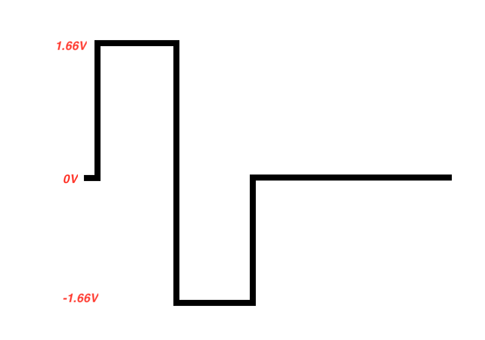
I wish to apply this design; I'm generating a -1.6 ~ 1.6V bi-phasic square pulse signal using an Arduino DUE's DAC by adding a highpass filter.
The signal will be reaching 1.6V or -1.6V for a short duration and the rest will be 0V during the period.

This signal's amp can be changed to increase or decrease the output current later on. The signal's frequency will be ranging to 50 ~ 8,000 Hz.
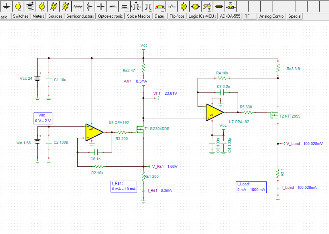
- Using the formula, I want no currents to flow when my input voltage signal is 0V.
- I want to generate a negative current using the above bi-phasic voltage pulse
- I will add a load resistor ranging from 500 ~ 1,000,000 Ω.
- My desired current amount is 100mA regardless of the load resistor.
- I have a power supply that can support up to 30 V.
So I want to change the Op Amp to TI's OPA445APG4.

How should I change the design in slau501 to achieve my requirements?
Suggesting a different TI's Op Amp, transistors, etc are welcomed and I will order them to implement it.
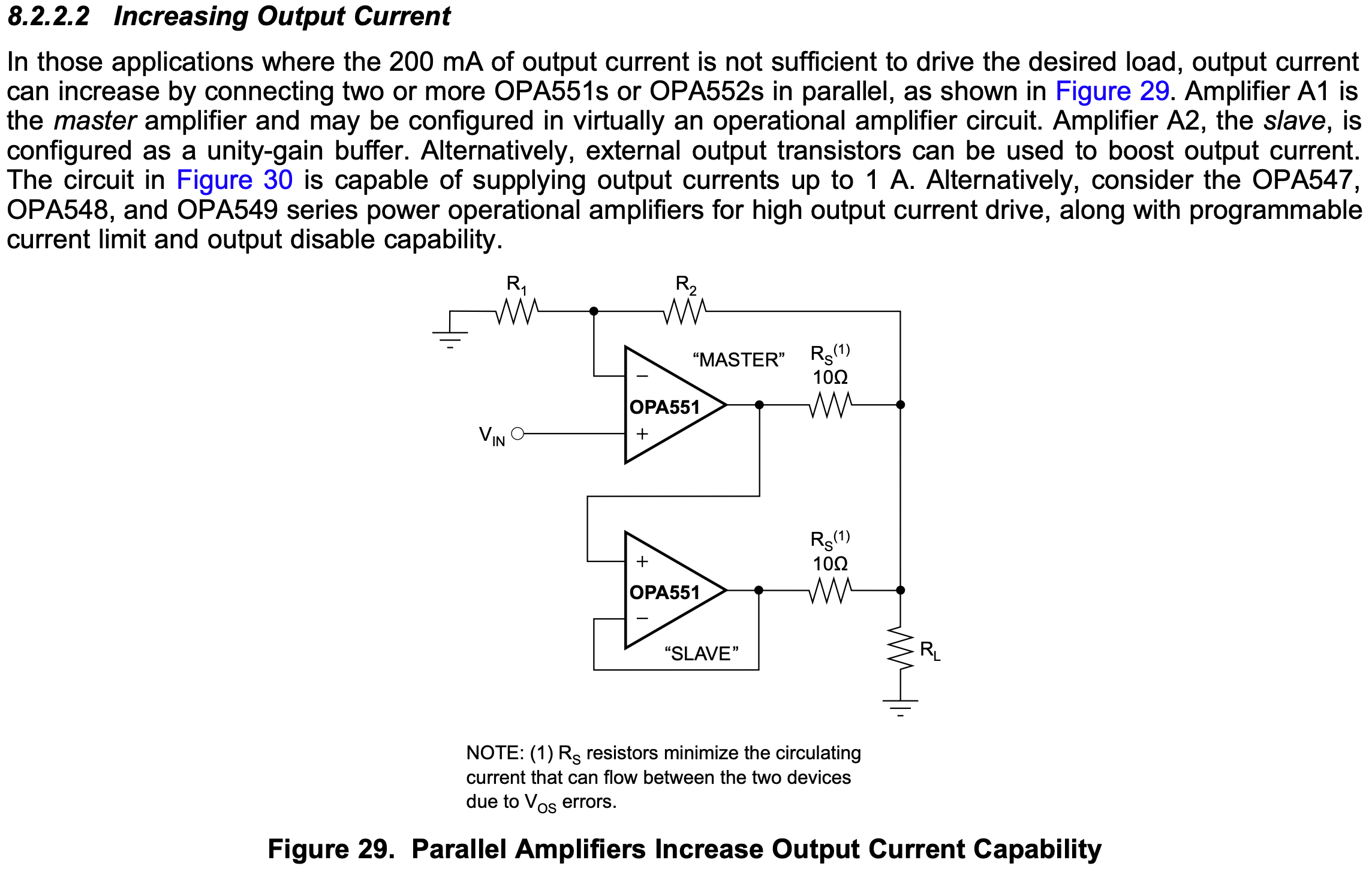
Or, if it is better to use TI's Voltage-to-Current converter ICs like this,
tell me, please.
-Thanks for your help