This thread has been locked.

If you have a related question, please click the "Ask a related question" button in the top right corner. The newly created question will be automatically linked to this question.

LMV324: output oscillation issue in LMV324

Part Number: LMV324
Other Parts Discussed in Thread: LM321, LMV321, TINA-TI, , , LM324, LM324LV, LM317

Hi all,

 My customer use LMV321 to replace their old LM321 in 1V voltage follower schematic (Vcc: 3.3V). In new design, high failure rate is happened (output oscillation, NG 6/50). Please check the attached pic for their circuit and test condition.

1. Except VCC range, any characteristic will impact the voltage follower design between LM321/LMV321?

2. Any comment about the oscillation? IC issue or design issue or?

Thanks for your response.

Best regards,

Gary Teng


  • Hi Gary,

    could you please post anoher photo better showing the cap values?

    Remove each cap sitting directly at the output of OPAmp. This cap will erode the phase margin and cause instability.

    Kai

  • Former Member
    0 Former Member

    Hello Gary,

    Thanks for your question.  My first suspicion is that the design was originally marginally stable, but with the change of parts the frequency response has shifted so that some of your circuits are now oscillating.  The bandwidth of both parts has the same typical specification, but it's possible they have a significantly different output impedance.  Given that it appears there is significant capacitive loading, this could be coming into play.

    As Kai has mentioned, it would help a lot if you could provide an image where the component values are easier to read.

    Regards,

    Daniel

  • Hi Kai and Daniel,

     Thanks for your response. Here's the clear pic about the circuit.

    Best regards,

    Gary

  • Hi Gary,

    I would run a TINA-TI simulation of your circuit.

    TINA-TI can be downloaded here and is for free:

    Kai

  • Former Member
    0 Former Member in reply to kai klaas69

    Hello Gary,

    My apologies for the late response.  After looking at your circuit, it is true that your output capacitors are very large and I am not surprised that you are having output oscillation issues.  Even though the circuit is set up for a DC output with DC input, it is important to consider the phase margin of the circuit.  If the phase margin is too small, then even small deviations from DC can cause oscillation.

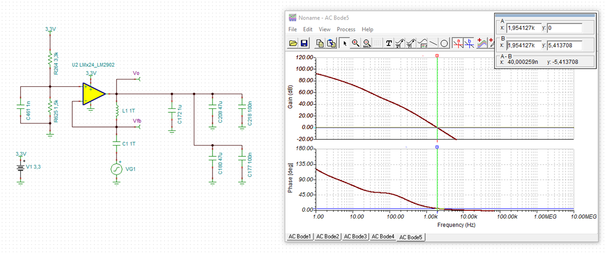
    I've run a simulation with the model for a similar part, the LMV324-N.  It has very similar specs, so we can expect it to give us some insight into what is going on.  Below is the file I used to run the simulation and the sim results.  As you can see, the phase margin is basically non-existent.  Have you considered removing output capacitance as Kai has mentioned?

    Gary.TSC

    Regards,

    Daniel

  • Hello Gary, Kai and Daniel,
    Thanks for your information.
    The LMV324 has the oscillation problem with a large output capacitor. 
    I have no idea if the LM324 has an oscillation problem in the same circuits.
    Could you please run LM324 simulation in same circuits and let us know the result? Thank you in advance.
  • Hi Gary,

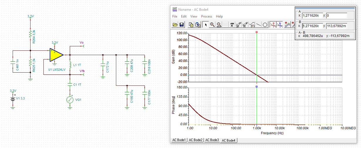
    neither the LM324 nor the LM324LV are stable:

    gary_lm324.TSC

    Kai

  • Sounds sad.

    By Hank's description, the output capacitor is required by next stage. But I think that might not be necessary for a sensitive voltage reference? 

    Hi Hank,

     What's your device using LM324 as voltage reference?

    Gary

  • Hi Gary, hi Hank,

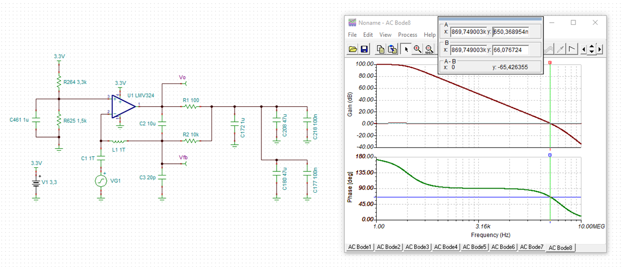
    a small isolation resistor can improve the situation:

    Another remedy is to use filtering caps with ESR (aluminium electrolytic or tantal):

    Another method is to use the "dual feedback" design discussed here:

    Kai

  • Former Member
    0 Former Member in reply to kai klaas69

    Hello Gary,

    Kai's analysis is correct.  Both devices will experience very marginal stability performance.  I'd like to point out that I made a mistake in the file I gave because I set the C172 load capacitor to 1uF instead of 100nF.  It is insignificant however, due to the other large loading capacitors, and I have verified this in simulation.

    The three methods Kai has suggested for improving stability and keeping the large cap load are good suggestions and may all be of interest to you.  I would only add that, if you choose to use the isolation resistor method, then you should take into account any potential voltage offset at the output that is caused by the resistor.  Given that it will probably be a very small value resistor, I doubt it is of great concern.

    Regards,

    Daniel

  • Hello All,
    I am sorry for replying late.
    The LM324 output is for reference voltage of the image sensor(CMOS type). The Iref current consumption is under 2mA. And the outside of Vref need 47uF cap. is suggested by the image sensor vendor.
  • Hi Hank,

    then I would go with the isolation resistor method. If the supply current is only 2mA, you might even be able to increase the isolation resistor above 1R. The higher the isolation resistor the more stable the circuit, at the cost of increased voltage drop due to the load current of image sensor of course:

    gary_lmv324.TSC

    Check out experimentally what resistor value is best suited in your application.

    Kai

  • Former Member
    0 Former Member in reply to Hank Chang1

    Thank you for the analysis Kai!

    Gary,

    I agree with Kai.  It will probably be the most straightforward solution for you.

    Regards,

    Daniel

  • Hello Kai and Daniel,
    Thanks for your information.
    Based on resistor isolation method,I adjust RISO resistor value to check output voltage is oscillation or not.The test result is as follows,

    RISO=0ohm, Voutput is oscillation.
    RISO=10ohm, Voutput is oscillation.
    RISO=50ohm, Voutput is oscillation.
    RISO=90ohm, Voutput is oscillation.
    RISO=100ohm, Voutput is flat.(The potential voltage offset around 3.4mV)
    RISO=150ohm, Voutput is flat.(The potential voltage offset around 4.5mV)


    I have below questions,
    1).Does RISO=150 ohm is good enough to prevent output oscillation ? How to judge?
    2).As you mentioned before, the "dual feedback" circuits. In our application, how to determine RISO, RF and CF ?
    Please let me know your opinion. Thank you very much.

    RISO.pdf

  • Hi Hank,

    sounds a bit strange that 100R are required to stop the oscillation.

    Is anything else connected to the output of LMV324 circuit during the measurement?

    Is the power supply of LMV324 clean, stable and noise-free?

    Does it make a difference whether you connect the scope probe directly to the circuit or via an 100R isolation resistor?

    Can you use such a spring scope probe for a test?

    Put the ground spring on a proper ground potential near the LMV324.

    Kai

  • Former Member
    0 Former Member in reply to Hank Chang1

    Hello Hank,

    I've re-run Kai's simulations from 1Ohm to 100Ohms and, while the higher resistor values show better phase performance at 100Hz to 10kHz, I don't think this is enough to justify having output oscillation up to 90Ohms.  I would recommend you try Kai's troubleshooting.

    To answer your questions:

    1.  To determine whether Riso = 150 Ohms is good enough, I would take a phase margin measurement.  This can be taken for a real world circuit indirectly using a transient overshoot test.  All you have to do is apply a step voltage to the input (such as 10mV), measure the percentage overshoot, and use that number to determine your phase margin.  Please see this presentation for instructions on how to do this: 

    2.  To pick the components for the dual feedback method, follow this process.  Note that the values here are for the example used in the presentation.  So, use the formulas but not the final result for Cf.

    You can learn more about the dual feedback method here: https://training.ti.com/ti-precision-labs-op-amps-stability-6?context=1139747-1139745-14685-1138805-13953

    In the meantime, I'm going to ask whether the LMV324-N model is similar enough to the LMV324 to serve as a suitable replacement in simulation.  I know you are looking to use the LMV324, but we have been using the LMV324-N for simulation.  I don't think it should matter, but I will double check.

    Regards,

    Daniel

  • Hello Kai and Daniel,
    Thank you for your information and below is my reply.

    Is anything else connected to the output of LMV324 circuit during the measurement?
    A:No, I have removed the external load.

    Is the power supply of LMV324 clean, stable and noise-free?
    A:The power supply of LMV324 is 3.3_SAV which same as input(CH1)'s power source. You can see the attached file RISO.pdf in previous reply.

    Can you use such a spring scope probe for a test?
    A: I have used spring scope probe for grounding and test again. The test result is same as previous one. Please refer RISO.pdf file in previous reply.

    Actually, the O/P that I use is LMV324IPWR. The LMV324IPWR has designed in our control board, each control board has 2 PCS LMV324IPWR. I have tested around 1000 PCS PCBA and there are 6 PCS LMV324IPWR output has oscillation problem. The above information is for your reference.

    Best Regards
    Hank

  • Former Member
    0 Former Member in reply to Hank Chang1

    Hello Hank,

    Thanks for your response.  I have a couple more requests.

    1.  From Riso.pdf, it looks like you are probing at the output of the circuit.  Would you mind probing at the output of the amplifier before Riso?

    2.  Would you mind sharing a scope shot of the power pin itself?

    Also, if the customer is still in the design phase you may consider the LM324LV part as it is newer and may get you a better pricing structure.

    Regards,

    Daniel

  • Hi Hank,

    I agree with Daniel. After having made lots of simulations with all available "324" models in the meantime, I can say that the "324" should just not do what you observe. And the plots shown in RISO.pdf are not typical for an oscillating OPAmp either. It looks more like an inteference coming from the +input of OPAmp or from the supply voltage pin which becomes filtered by Riso and the capacitive load. This would explain why the amplitude of "oscillation" is decreasing the more the more Riso increases. And since the +input seems to be clean, the interference can only come from the positive supply pin. Remember that the +input gets a low pass filtered copy of the suppy voltage because of C461!

    So, please show us a scope plot of the "3.3V_SAV" line. And please also tell us the value of C461.

    Kai

  • Hello Kai and Daniel,
    Thank you for continuing focus on this issue.
    Based on your suggestion, I measure the amplifier before Riso and power pin of LMV324. Please refer the attached file.
    The C461 is 1uF.

    The test result is as follows,
    RISO=0ohm, Vc is oscillation.
    RISO=10ohm, Vc is oscillation.
    RISO=50ohm, Vc is oscillation.
    RISO=90ohm, Vc is flat.
    RISO=100ohm, Vc is flat.
    RISO=150ohm, Vc is flat.

    RISO_r1.pdf

    BTW, I also check the NS version LMV324 datasheet, there is a "high compliance current sink" circuits. Does this circuit can apply in
    my application? Could you please run simulation on this case and let me know your opinion ? Thank you in-advance.

    LMV324.pdf

    high compliance current sink.pptx

  • Former Member
    0 Former Member in reply to Hank Chang1

    Hello Hank,

    Thank you for your patience and for providing your results.  This is quite helpful to understanding the problem better.

    I think what is most bizarre is that the output oscillation is worse with a small isolation resistor (~10 Ohms) than with no isolation resistor.  The output of the amplifier even appears to slam into the rail.  I would say that the voltage supply is not totally clean of noise, but I'm not sure it's bad enough to explain the type of behavior you are seeing.

    From your original post, it seems that this is only a problem on 6 out of 50 units.  Is that correct?  We may need to have me try to rebuild it here and see if I can reproduce the result.  However, it seems like you are only having the problem on certain units.

    Is there anything else loading the op amp at the "UP_VREF_1.0V" node?  Is the op amp driving an ADC?  Can you disconnect the "UP_VREF_1.0V" node from the rest of the circuit after?  You may even wish to remove the problematic units from your board and rebuild the circuit with the problematic units on a different board, but with nothing else loading the "UP_VREF_1.0V" node.

    Please let me know if this all makes sense.  If we cannot debug the issue, would it be too late to switch to the LM324LV device?

    Regarding your last question, the "high compliance current sink" circuit should not apply in your scenario since you are simply loading with capacitors.

    Regards,

    Daniel

  • Hi Hank,

    I agree with Daniel. Your latest measurements are exemplary. And what is happening is very strange. I also agree with Daniel that the supply voltage of OPAmp ("3.3V_SAV" line) is not as clean as it should be. It seems that the OPAmp is powered by a switcher? Switchers are known to cause lots of problems unless very good input and output filtering is provided. So, I would suggest to improve the supply voltage performance of OPAmp. Use a linear voltage regulator like the LM317 for a test. And disconnect everything of the rest circuitry from the OPAmp section. Assure that only the OPAmp circuit is running and nothing else!!

    Always keep in mind that an OPAmp needs a clean, stable and noise-free supply voltage! If this rule is violated, the strangest things can happen...

    Good luck :-)

    Kai

  • Former Member
    0 Former Member in reply to Former Member

    Hello Hank,

    I have not heard back from you in a while.  Has your issue been resolved?

    If not, feel free to post here and we will try to help you out.  Otherwise, I will assume that you've found a resolution.

    Regards,

    Daniel

  • Hello Daniel and Kai,

    Based on your suggestion and testing results, we make decision to modify the circuits by Riso + dual feedback type.
    The parameters are as follows, Riso=100 ohm, Rf=10K ohm, Cf=10uF.

    I really appreciate your help, thank you again.

    Best Regards
    Hank

  • Former Member
    0 Former Member in reply to Hank Chang1

    Hank,

    Please feel free to reach out again if you need any further help!

    Regards,

    Daniel

  • Hi Hank,

    good decision.

    hank_lmv324.TSC

    Kai

  • Former Member
    0 Former Member in reply to kai klaas69

    Thanks for the analysis Kai!

    I went ahead and re-ran the simulation with the input capacitance of the part included, for the sake of being thorough, and got very similar results.

    Regards,

    Daniel