This thread has been locked.

If you have a related question, please click the "Ask a related question" button in the top right corner. The newly created question will be automatically linked to this question.

TPS2412:mosfet half on

Part Number: TPS2412
Other Parts Discussed in Thread: TPS2413

Hi team,

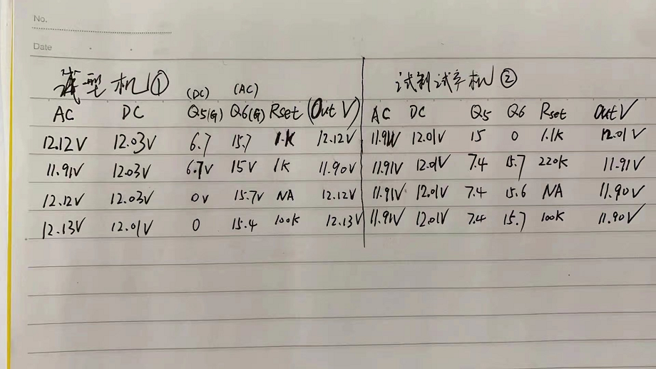
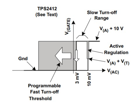
My customer uses two TPS2412 for input ORing application, see datasheet Fig.10.

However, they met a problem that during normal operation, the low-voltage bus MOSFET was half on (should be off), they measured the gate voltage which was about 6V (should be 0V).

  1. They use RSET=220kohm here. Is this problem related to RSET?
  2. How to let the MOSFET of low-voltage bus become off instead of half on?

  • Customer tested two failed boards, the data are below.

    AC is one input bus, with MOS Q6.

    DC is the other input bus, with MOS Q5

    We can see that:

    For 1st board, use Rset=100kohm or NA can solve the problem, Q5 could turn off (gate voltage is zero).

    For 2rd board, use Rset=1.1kohm can solve the problem, Q5 could turn off (gate voltage is zero), but 1.1kohm is beyond range (datasheet mentions that Rset should be 1.5kohm to ∞.

    Still didn't get a good solution. 

  • Hi Miranda,

    Thanks for reaching out to us. I will work on your query and get back to you by early next week.

  • Hi Miranda,

    TPS2412 has linear Gate control. The gate voltage is regulated to maintain 10 mV ('TPS2412 forward turnon and regulation voltage') across the FET. 

    In case you want ON/OFF control you can consider using TPS2413. 

    To understand more about Linear Gate control, please refer to section '6.1 Linear Regulation Control Vs Hysteretic ON/OFF Control' in 'Basics of Ideal Diodes' app note

  • Hi Praveen,

    Many thanks for your prompt reply!

    Just two additional question:

    1. From customer's test results, the Rset value is related to gate voltage, could you please give an explanation why is that?

    2. What's the bad impact using TPS2412 linear control compared with TPS2413 on/off control? More power loss? If no bad impact, customer may keep using TPS2412.

  • Hi Miranda,

    Rset value programs the reverse turn OFF threshold. This is the reason why the Gate turns OFF for few Rset values as the reverse turn OFF threshold is very low. You can use the formulae below to calculate the  threshold value.


    Yes, the only disadvantage of having linear gate control is power loss and voltage drop.

  • Hi Praveen,

    Thanks for your explanation.

    My understanding is below.

    • When Va_c below Voff (set by Rset), the gate voltage will be zero, the FET will be turned off.
    • When Va_c beyond 10mV, gate voltage will be Va+10.2V (when Vdd=12V), the FET will be turned on.
    • When Va_c between Voff and 10mV, the gate voltage will be linear controlled, the FET will be half on.

    Please correct me if I am wrong.

    The wield thing is that customer measured the gate voltage was about 15~16V, from my understanding the gate voltage should be Va+10.2=22.2V. Why is that? Do you have any ideas?

  • Hi Miranda,

    Yes, your understanding below is correct.

    • When Va_c below Voff (set by Rset), the gate voltage will be zero, the FET will be turned off.
    • When Va_c beyond 10mV, gate voltage will be Va+10.2V (when Vdd=12V), the FET will be turned on.
    • When Va_c between Voff and 10mV, the gate voltage will be linear controlled, the FET gate will be regulated to maintain Va_c = 10 mV.

    What is the load current when you have taken these measurements. Remember Va_c is a function of load current x Rds(on). In linear region the Gate voltage will vary to maintain a Va_c of 10 mV across the FET. Try increasing the load current to see variation in gate voltage.

  • Hi Praveen,

    I did tests on EVM board, the results are same as customer's board. So it's not an issue.

    Thanks for your help!