This thread has been locked.

If you have a related question, please click the "Ask a related question" button in the top right corner. The newly created question will be automatically linked to this question.

Grounding or Reference Potential for INA116

Other Parts Discussed in Thread: INA116, INA118, INA333

Hi all,

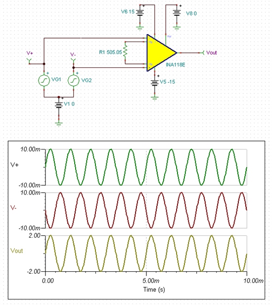
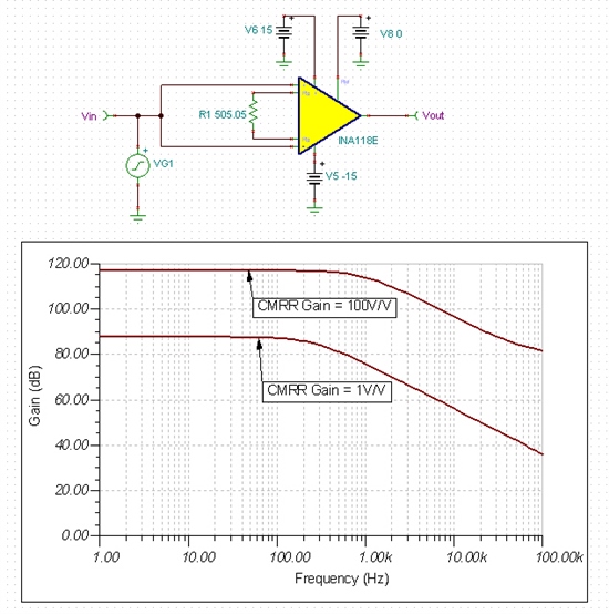
I have done some experiments with the INA116 and could not understand some of the phenomenons.  I was trying to understand the common-mode rejection capability of the IA.  I have tried three different configurations and the schematics are as below.  I was using a signal generator to produce a 32kHz sine wave with amplitude of 200mV.  The gain of INA116 is set to 10.  


In scenario A, the ground of the signal is connected to the ground of the INA116.  The output signal is good as expected.  In scenario B, I purposely made sure that the ground of the signal from signal generator is not connected to the ground of the INA116.  As INA116 is a differential amplifier it should be able to amplify the difference, which is the signal although the grounds are not shared between two systems.  However, the output is very wrong.  I see very big noise and very unstable signals shown as below.  

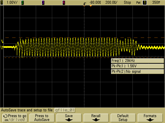
In scenario C, I was connecting two grounds with a 1Meg resistor to simulate when two systems grounds are not well connected together.  The result is same as scenario B.  

So my questions are:

1. Is there are something wrong with the IA so it is not able to amplify the difference between two inputs and disregard the common mode voltage?

2. Or is there something wrong with my test methods?  What shall I do if I want to amplify some differential signal whose reference could be not connected to IA ground?

Thanks indeed.

Best Regards,

Jianglei


  • Hello Jianglei,

    I believe the answer has to do with scenario 2 and your test method.  Your souce is a single-ended source, not a differential one and therein lies the issue.  You need to provide a low-impedance reference for the GND of the signal generator and connecting it to the high-impedance inputs of the INA doesn't work.  If you can set up two sources and synchronize them together 180 degrees out of phase with a shared GND then you should be able to test the CMRR of the part by adjusting the DC offset of the two signals together.  The differential output should not change as long as the differential voltage does not change.  An example of this test can be seen in the following images with the INA118.  Testing the INA116 will be similar.

    The two sources are setup 180 degrees out of phase.  A DC offset of 0V is applied first, the output is +/-2V. 


    Now increase the DC offset to 5V.  The output is still +/-2V.

    Also, if you desire an AC CMRR measurement, simply tie the inputs together inject an AC signal and monitor the output.  The CMRR will be (20*log(Vin/Vo))/Gain , where "Gain" is the INA gain.  Please see an example in the following circuit:


    Best Regards,
    Collin Wells
    Precision Linear

  • Jianglei,

    Everything that Collin has provided is true but perhaps I can add some explanation that will help.

    It is very unusual to have input circuitry that is totally floating or disconnected from the amplifier ground. Totally disconnected, as you show it, there is nothing to define the voltage of the inputs with respect to the ground of the INA116. Thus, the inputs can "float" to a potential that is outside the common-mode range of the INA116. The differential input voltage is defined by your 32kHz signal but the common-mode voltage is not defined.

    It is clear that in your case, 50Hz noise from the mains is causing the common-mode input voltage to move inside and outside the linear range of the INA116. Thus, for brief periods every 10ms, the inputs come into linear operation and then swing outside the linear limits of the amplifier.

    So in most any instrumentation amplifier application, some impedance must connect the input voltage sources to the amplifier ground to keep it within the common-mode range. You tried a 1M-ohm resistor. Clearly the noise from the mains on the generator connected to the input is still sufficient exceed the common-mode input range of the INA116.

    Regards and I hope this helps,  Bruce.

  • Hi Bruce & Collin,

    Thanks indeed for your reply and now I'm clear how it works. 

    Best Regards,

    Jianglei

  • Hi Bruce,

    I have similar circuit wherein I connect the output of a function generator to the input pins of INA333.

    I am applying Vref at input to meet with the common mode requirement .Here the function generator ground is no way connected to the circuit ground.

    As a result the output is not perfectly stable.Can you suggest a workaround.

  • Dilbagh,

    I want to avoid confusion with this thread and duplication of John's support of your question. You can expect a reply and clarification on your original thread.

    Regards, Bruce