This thread has been locked.

If you have a related question, please click the "Ask a related question" button in the top right corner. The newly created question will be automatically linked to this question.

OPA847 Stability

Other Parts Discussed in Thread: OPA656, OPA847, THS3201, OPA846, TINA-TI, LMH6551

Dear all,

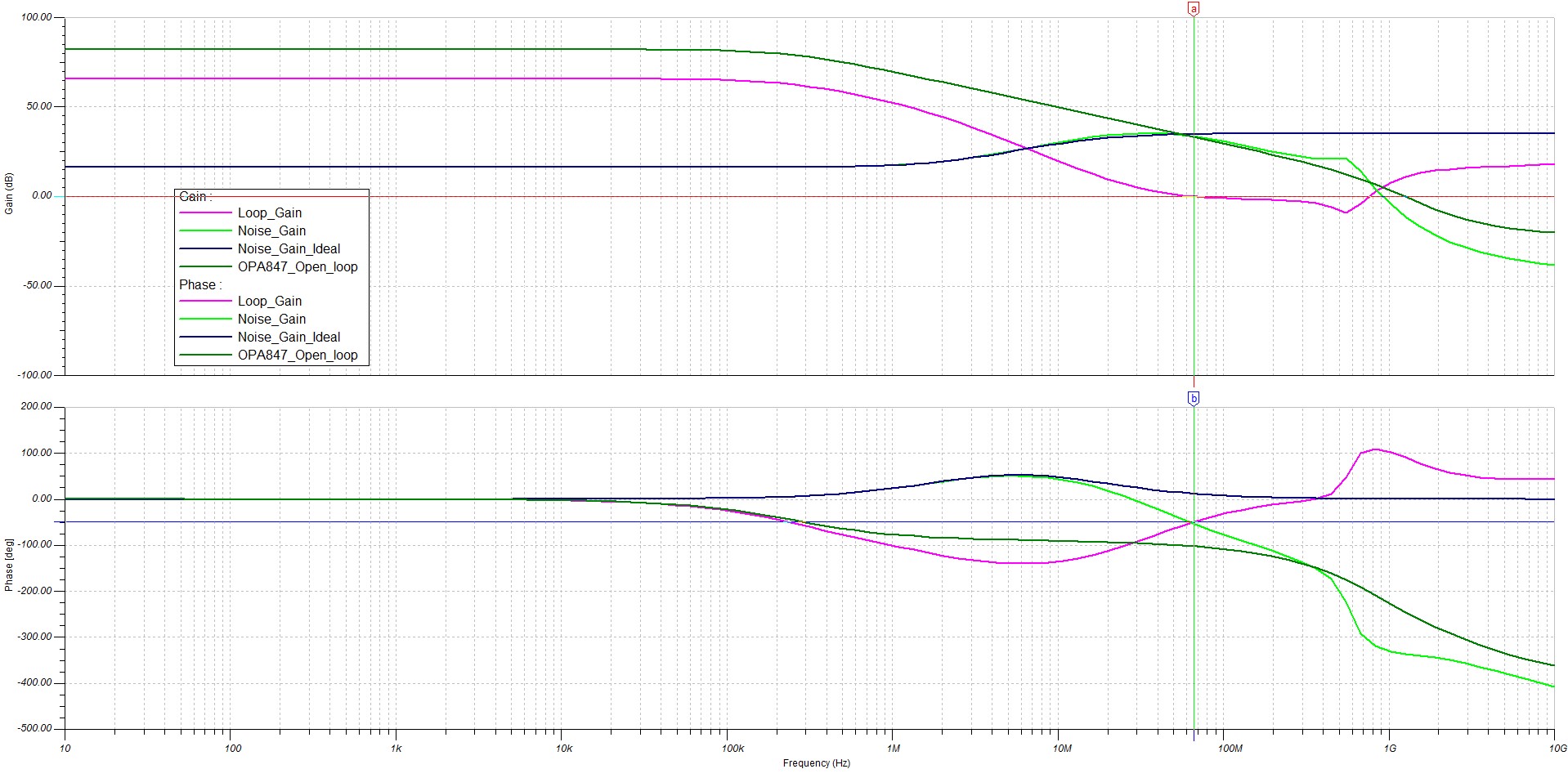
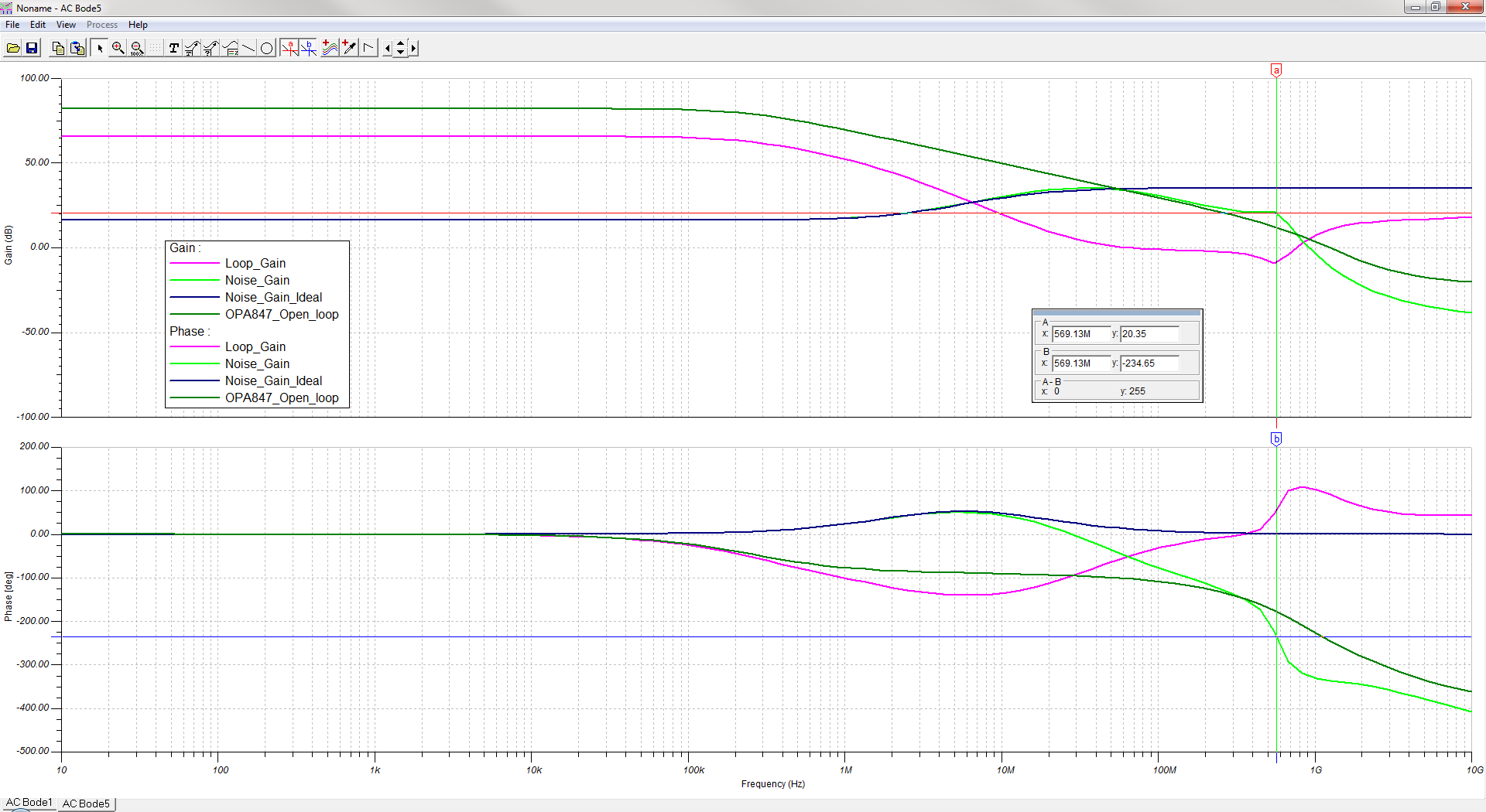
I have been working on a design for some time which uses the OPA847 in a transimpedance configuration. The problem is making the amplifier circuit stable against parasitic oscillation. Specifically, the amplifier shows significant overshoot in the response when amplifying the signal from a photodiode which is subject to very short pulses of light. I have attempted to cure this by adding a very small amount of feedback capacitance (about 0.5pF). However, any appreciable feedback capacitance causes the amplifier circuit to go into oscillation before the overshoot is reduced to a satisfactory level. Lower bandwidth op-amps such as the OPA656 can be made stable but have been found to have insufficient bandwidth for the application.


The PCB is double sided and has been designed with all the usual precautions to minimise stray capacitance. Voltage supplies to the op-amp have been decoupled.


Any help on this matter would be much appreciated.


  • Hi

    I'm working on a similar subject to yours, designing a pre-amplifier for a MPPC detector (MAPD) and I have also been using the OPA847.


    What is your light source pulse lenght, hence your required rise time/BW?

  • Dear Stian,


    Required transimpedance bandwidth is about 100MHz minimum.


  • Hi Merlin,

    A stability analysis for tranimspedance circuit is shown in the attached application note: http://focus.ti.com/general/docs/litabsmultiplefilelist.tsp?literatureNumber=sboa122.  In general it will depend on the transimepdance gain, expected bandwidth, source capacitance and gain bandwidth product of the amplifier.

    In your case, you may not have any source capacitance to use a 0.5pF feedback capacitance.

    Can you send me your full schematic, photodiode capacitance as well as layout for my review at x-ramus2@ti.com.


  • @ Stian Scisly Sagevik -- by MAPD, are you referring to the the Silicon Photomultiplier devices ? If yes, do you mind sharing your circuit. I find them to be interesting devices and am working on similar devices.

    Thanks in advance.


  • I have sent you a "private" message.

  • would also be interested in your design. I'm working in the same field.

  • I'm having the same type of issues and would be very happy if you could share with me too. Thanks! -Peter

  • Hello Pete,

    Can you send your schematic and describe the issue you are having with the OPA847?


  • me too. Pls also share to me your experiences! thank you

    lonzhang

  • THS3201 current feedbcak opamp seems to work fine in transimpedance configuration with feedback resistance of 470-1000 ohm , another alternative is to use THS3203 differential amplifier with 10 hm current sense resistor on the input. Generally, the nest way to improve the stabilty of transimpedance amplifier when dealing with SiPm is to insert some 10 ohm series  resistor into the input node.


  • sorry meant THS4203 not THS3203..


  • Merlin,

     I am working on a similar TI circuit using the OPA 827 and I am experiencing the same problems as you have described in this post. Was there a conclusion to this thread? And if so could you reply with a working circuit schematic and any tricks that helped you to stabilize this circuit.

    Thank you

    Pete Arslanian

  • Hi,

    me too I would be interested in knowing the conclusion for this thread... I am getting crazy with the oscillations and there is no way to make them disappear. Could you please share the solution? My problem is that as soon as I put any feedback capacitor, the output starts to oscillate at around 650MHz.

    Thanks,

    Isaac

  • Hello Isaac,

     Can you please send me your schematic for the application circuit, along with expected photo-diode capacitance and transimpedance gain you are trying to achieve.

    -Samir

  • Hello All,

    With non-unity gain devices (like the OPA846 and the OPA847) in a transimpedance configuration, if you raise the feedback capacitor too high, you can lower the Noise Gain pole frequency such that the crossover frequency can occur at below the minimum stable gain of the device (i.e. 7V/V for the OPA846 and 12V/V for the OPA847). This could cause instability in and of itself! Not enough feedback capacitance, could lead to instability due to excess phase shift around the loop (which is a different mechanism) due to the action of the feedback resistor looking into the amplifier inverting input capacitance. So, there is an optimum value for CF.

    You can use TINA-TI simulation to predict this effect as outlined in this post:

    http://e2e.ti.com/support/amplifiers/high_speed_amplifiers/f/10/t/333642.aspx

    The image below shows simulated Noise Gain and Open Loop response with CF varied (0.3pF, 1pF, and 3pF) using OPA847. You can see that 0.3pF is not high enough and the rate of closure is about 40dB/ decade and OPA847 will be unstable. With CF= 3pF, the Noise Gain intercepts the open loop gain at close to 483.2MHz where the open loop gain is about 14.1dB (=5.1V/V) which is below the 12V/V minimum stable gain of the OPA847. CF of 1pF is just about right in satisfying both the minimum stable gain criteria as well as 20dB/decade rate of closure (indicative of excessive external phase shift).

    Here is the TINA-TI circuit for above image:

    0246.OPA847 TIA Open Loop Analysis E2E Hooman stepped 4_21_14.TSC

    Regards,

    Hooman

  • Hi Samir,

    sorry for the late reply. Here you have my circuit together with the Bode plots. I followed the steps indicated in another post by your colleague Hooman Hashemi (http://e2e.ti.com/support/amplifiers/high_speed_amplifiers/f/10/t/333642.aspx).

    As you can see in the bode plot, the Loop_Gain curve has a phase of -50º at 0dB crossing (66MHz) which means that there is still a big phase margin. However, in the Noise_Gain curve, which is extracted using the OPA847 model as shown in the schematic, there is a strange peak @ 570MHz that I did not expect. I took into acount that this OPA847 is stable for gains >12V/V and this is also respected as seen in the plots where the point where the noise gain joins the open loop gain I have around 50dB.

    The problem comes when I implement the my transimpedance amplifier and I put this Cf value in it. AT that moment, the ouput of the transimpedance amplifier starts to oscillate at a frequency 670MHz which is quite close to the peak found in the noise gain curve in the simulation. I don't understand why this peak comes up where I expected to have the noise gain gently following the open loop gain after 1/(2*Pi*Cf*Rf).

    Could you please give some advice on that?

    Thanks,

    Isaac

  • Hello Isaac,

     From your schematic it looks like your Shunt Resistance of the photo-diode is 100Ohms and the Junction Cap of the photo-diode is 950pF. Are you sure these numbers are accurate?

    Samir

  • Hello Samir,

    in fact this 950pF is just the capacitance of just one channel of the silicon photomultiplier I have to use (around 1cm2 of total area). It has in total four channels and around 950pF/channel. In the 100 Ohms resistor is an external resistor and not the shunt resistance of the SiPM.

  • Isaac,

    Couple of issues that I need clarification on:

    1. Can you please double-check if it is a 100Ohm series or shunt resistor between the photo-multiplier junction capacitance and the inverting input of the amplifer?

    2. I notice that you have a Noise-gain curve wherein you have used the OPA847 model as opposed to an ideal opamp. You really cannot use this curve to estimate your phase margin or predict circuit behavior. The reason is because the open-loop gain curve of the OPA847 interacts and affects your noise gain curve. This is why we separate the 2 effects out - a) Open loop gain curve of the OPA847 and b) Ideal Noise gain curve using ideal opamp gives you the 1/beta factor. When you divide the two curves you get the A x Beta = Loop Gain Plot which is used to model stability.

    Hope this makes sense

    Samir

  • Dear Samir,

    1. It is a 100Ohms shunt resistor (connected between the photodiode cathode and ground). How can it affect to the transimpedance amplifier response?

    2. I see you point and I thought I should use the OPA847 model also for looking at the noise gain in order to see the most "real" response of the circuit since this is what I am going to have in the real implementation.

    Still, I don't know what is making the circuit oscillating if in the simulation, the Cf value seems to work properly...

    Cheers,

    Isaac

  • Hello Isaac,

    1. I played with the numbers for the 100Ohm shunt resistor and dont see an issue. With the 950pF capacitor in parallel the effects of the 100Ohm arent critical at the frequencies where the AOL starts to droop.

    Now with regards to the oscillation, is it possible that there is load capacitance that you are not taking into account in your simulation which may be pushing the amplifier into instability?

    Can you bump up the feedback capacitance to around 30pF and see if it removes the oscillation? What I am trying to do with the 30pF is trying to get your loop gain crossover to be about mid-way between the pole in the 1/beta of the noise gain curve and the 2nd pole in the Aol of the OPA847. This seems to have a small improvement on the phase margin; it also seems to reduce the sag in the phase at the lower frequencies.

    Could you please send me a screenshot of the oscillations?

    Thanks,

    Samir

  • Hello Samir,

    here I attached the full readout channel. After the transimpedance amplifier, there is a differential stage using the LMH6551 to send the signals to the readout boards. However, while testing the circuit, they are going to a scope with the channel teminated at 50Ohms.

    I will try to mount a capacitance close to 30pF but if I remember correctly I already tried with values close it. However, I will try it again. Here you have the oscillations I see in the scope:

    In the screenshot, the BW is limited on the scope but if I use the full BW of the scope then I have even wider oscillations with an amplitude of 20mVpp or even more.

    Thanks,

    Isaac

  • Hi Isaac,

    Thanks for the detailed explanation. I reran the simulation with the 100Ohm load resistor and it seems to have minimal effect on the loop gain response. I do not have a photo-multiplier tube that I can use in my circuit, however what I would like to do is to test the OPA847 in the lab here with 950pF & 100Ohm shunt and 560Ohm and 17pF feedback,  with a 100Ohm load resistor.

    1. Can you please confirm that even with the PM un-excited you see the oscillations?

    2. Also, please disconnect the TIA from the LMH6551 circuit and confirm the oscillations are still there.

    3. When testing with the scope is the scope 50Ohm terminated or high impedance terminated? I would recommend putting it in the High Z mode if you arent already doing so.

    4. Finally, when probing the output with the scope are you probing directly on the output of the TIA? This will add some load capacitance on the output, so I would add some series resistance to the scope probe(use a 500Ohm through-hole resistor). This will isolate any probe capacitance from the scope output. I ran a simulation with a 10pF load cap and I do see a strange peaking at around 580MHz. I have attached my simulation with this email.

    Thanks,

    Samir


    3414.TIA Open Loop Analysis - NoSweep.TSC

    Thanks,
    Samir


  • Hello Samir,

    1. Yes, even without having it connected to the input of the OPA847, I can see the oscillations. The only way I don't see the oscillations is by removing the feedback capacitor. Once I try to put any feedback capacitor, the output starts to oscillate.

    I also have to say that I tried the circuit without the connecting the photodiode, with it connected without biasing it (it has around 2nF of capacitance) and biasing it (it has around 950pF). The oscillation is always there at the output of the differential stage.

    2. I am going to do it as soon as possible and see if the oscillations disappear.

    3. If I measure at the output of the LMH6551 then I terminate the scope at 50Ohms since the output impedance of the LMH6551 is configured at 50Ohms. However, I will terminate the probe to high Z while probing directly the output of the TIA and also I will use the 500Ohms series resistor as you advised me.

    4. About the peaking in the simulation, I really don't know how to interpret it... I was wondering if this is an effect popping up due to such big capacitance at the inverting input of the OPA847. Like a third-order effect hidden while using lower levels of capacitance at the inverting input but getting dominant as long as this capacitance value gets increased...

    I would appreciate any help since this could be a show stopper for our project given the fact that we cannot tune at all the response in frequency of our TIA and we are getting big overshoots in our signals that really annoy the data analysis....

    Thanks,

    Isaac

  • Hello Isaac,

       We tried all day yesterday to come up with method to stabilize the OPA847 with RF = 100Ohms and Cin = 950pF, but were unsuccessful in stabilizing. Similar to what you saw,  with no feedback capacitance it looked to have very tiny oscillations and with 10-30pF capacitance we observed oscillations in the 660MHz range. For capacitances in the 1pF-5pF range we saw large signal oscillations in the 5MHz range.

    We consulted with some of the senior engineers and on their advice modified our TINA model to have a series 3nH inductor in series with the 950pF Cin. If you plug that into the simulation you will notice the noise gain characteristic starts to do some very funny things which affects the loop gain of the TIA. The 3nH is meant to simulate trace and bond-wire parasitic inductance as well as any lead inductance from the PMT with its parasitic cap. Usually we ignore these inductances, however because of the large Cin it creates  resonance at much lower frequency values.I  believe this is why we are having such a hard time stabilizing the part.

    Could you let us know what the bandwidth of your application is so that we might be able to suggest a different opamp? Also, what is the model of the PMT you are using?

    Samir

  • Hi Samir,

    thanks for you research and what you mentioned about the inductance makes sense to me. In fact, we have like 30nH of connector+PCB traces inductance until arriving to the OPA847... this is really bad if the instability behavior is dominated by this series inductance. I ran the simulation to see what was going on in the loop gain and yes, it has quite a strange behavior due to the resonance.

    • The bandwidth we need is around 80MHz and we would like also to have low noise levels like the OPA847. It would be really good if you could provide us any advice on which opamp could do the job for our application. We need to fix this issue we are having as soon as possible.

    We are using a silicon photo-multiplier from Hamamatsu but it is not a on the shelf product. It is something we are developing together but I could give you as many specs as you need.

    Thanks and I look forward to hearing from you,

    Isaac

  • Hello Isaac,

    Is there any way to get the amplifier right up to the photo-diode? The series inductance is a real killer if we need this to work. Also, when you mention an 80MHz bandwidth, is this the 3db bandwidth of the amplifier? Or is it the unity gain transimpedance bandwidth?

    Regards,

    Samir

  • Dear Samir,

    it is quite difficult to reduce the distance between the two and even with that, I don't feel myself confident to have a satisfactory results. As you mentioned, just with 3nH of series inductance (parasitics) and due to this big capacitance, it is likely to have oscillations.

    The 3dB bandwidth that we would like to have is 80MHz. Let's see if we could find something to solve this issue...

    Thanks,

    Isaac

  • Hello Isaac,

    Well i am facing the same problem as yours, did you solve the problem ?

    Thank you,

    Mouhamad.
  • Hello Mouhamad,

    are you using the OPA847 for the same application, as a pre-amplifier of a large area silicon detector? In our case, we played with other parameters on the detector side to finally have the desired response. At least for us, no way to tune the frequency response of the transimpedance amplifier using the OPA847 with such input capacitance.

    Let me know if you are using the OPA847 in an application similar to ours.

    Cheers,

    Isaac