Other Parts Discussed in Thread: OPA615,
Hi,
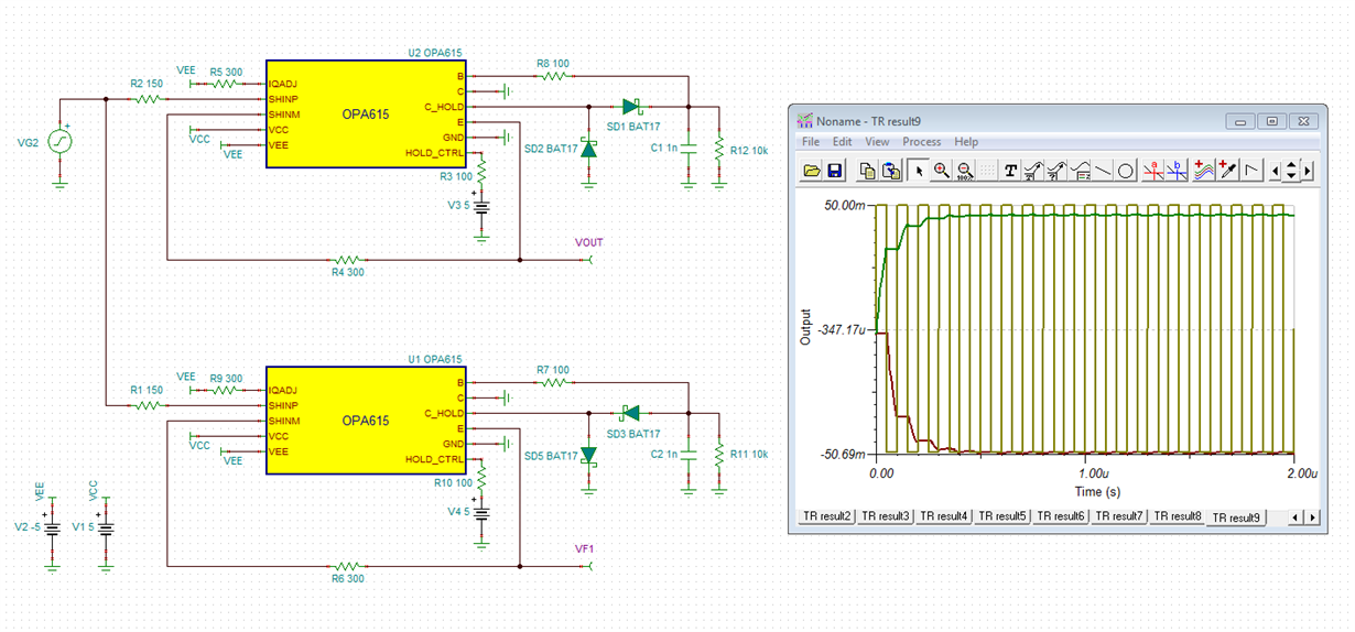
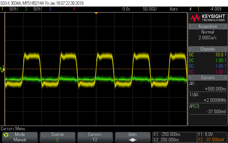
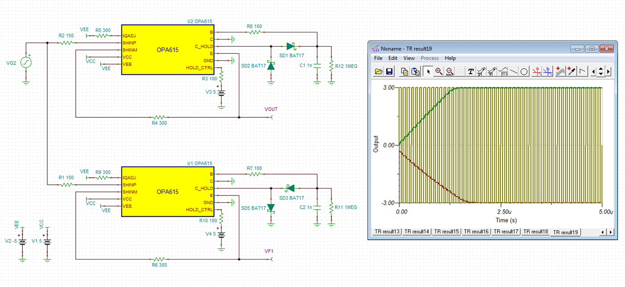
I'm trying to build a peak detector used for square wave @10MHz and the amplitude as low as 100mVpp. I followed the circuit in the OPA615 datasheet but run into the following issues:
1. The positive peak detector has a drop of ~5 to 10mV depending on the diodes being used. So far, I found that the diode JDH2S02SL gives the least drop.
2. Negative peak detector circuit is not working. I've tried both simulation and LAB. This leads to issue #3
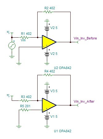
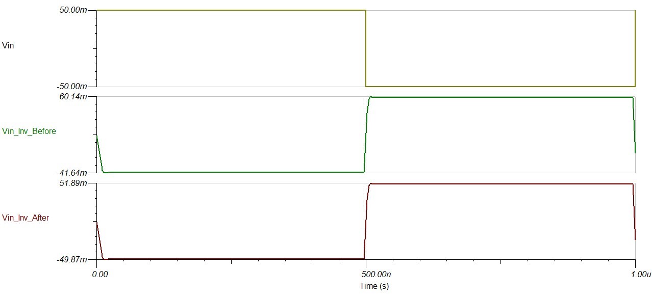
3. So in order to detect the negative peak, I'm trying to use the OPA842 to flip the input signal (G = -1). However, I can't seem to calculate the resistor connected to the non-inverting OPA842 input. The circuit i use is also from OPA842 datasheet (datasheet circuit has a gain of -2 instead). They do mention briefly about that resistor calculation but i can't figure out how.
So my questions are:
1. Do you have any suggestions to achieve a better peak result?
2. How to calculate the resistor connected to non-inverting OPA842 when configured as G = -1?
Here's my simulation from LTspice:
PSpice models used:
*-----------------------------------------------------------------------
* OPA842 Wideband,  Low Noise Voltage Feedback Op Amp
* Created 5/1/03    RS
*
*
* NOTES:
*   1- Uses a multiple pole-zero topology
*   2- For better convergence during transient analysis set:
*        .OPTIONS  ITL4=40
*   3- This macromodel predicts room temperature performance
*      (T = 27 deg C) for: DC, small-signal AC, noise, and
*      transient simulations
*   4- This macromodel does not predict: distortion
*      (harmonic, intermod, diff. gain & phase, ...),
*      temperature effects, board parasitics, differences
*      between package styles, and process changes
*
* |---------------------------------------------------------------|
* |  This macro model is being supplied as an aid to              |
* |  circuit designs.  While it reflects reasonably close         |
* |  similarity to the actual device in terms of performance,     |
* |  it is not suggested as a replacement for breadboarding.      |
* |  Simulation should be used as a forerunner or a supplement    |
* |  to traditional lab testing.                                  |
* |                                                               |
* |  Neither this library nor any part may be copied without      |
* |  the express written consent of Texas Instruments Corporation.|
* |---------------------------------------------------------------|
*
* CONNECTIONS:
*              Non-Inverting Input
*              | Inverting Input
*              | |  Positive Power Supply
*              | |  |  Negative Power Supply
*              | |  |  |  Output
*              | |  |  |  |
*              | |  |  |  |
.SUBCKT OPA842 + -  V+ V- Out

V_V1         V+ 10 DC 1.4
E_E3         21 22 POLY(2) 0 18  V+ V- -785m 1 0.5
E_E4         24 25 POLY(2) 18 0  V+ V- -785M 1 0.5
D_D1         16 15 DX 1
D_D3         18 20 DX 1
D_D5         23 24 DX 1
D_D7         0 27 DN1 .5
I_I3         27 26 DC 100uA
I_I4         29 28 DC 100uA
D_D2         19 18 DX 1
R_R16         21 V+  45
R_R17         V- 25  45
R_R18         23 Out  5
D_D8         28 0 DN1 .5
D_D9         0 29 DN1 .5
D_D6         26 0 DN1 .5
R_R14         17 0  1000K
G_G3         0 17 POLY(1) 12 11 0 50M 0 0
G_G4         0 18 POLY(1) 17 0 0 1M 0 0
R_R15         18 0  1K
R_R12         15 13  75
R_R13         15 14  75
R_R10         11 10  750
R_R11         12 10  750
I_I1         15 V- DC 3.1mA
D_D4         22 23 DX 1
E_E1         19 0 POLY(1) V- V+ .5 0.5 0 0
E_E2         20 0 POLY(1) V+ V- -1.0 0.5 0 0
V_V2         16 V- DC 1.5
G_G2         2 0 POLY(2) 28 0 29 0 0 .001m .001m
G_G1         + 0 POLY(2) 26 0 27 0 0 .001m .001m
Q_Q1         11 + 13 QN 12
Q_Q2         12 2 14 QN 11.867
I_I2         V+ V- DC 15.7mA
C_C2         17 0  200p
L_L5         2 -  2.46nH
C_C13         0 2  1p

*
.MODEL DX D(IS=1.0000E-15)
.MODEL DN1 D(IS=2F AF=1 KF=10.5E-17)
* QN NPN model
.MODEL QN NPN
+ IS=7.6E-18
+ VAF=78.71
+ VAR=1.452
+ BF=157
+ RB=1.20E+02
+ KF=9.5E-15
+ AF= 1.0

.ENDS    OPA842


