This thread has been locked.

If you have a related question, please click the "Ask a related question" button in the top right corner. The newly created question will be automatically linked to this question.

Heat problem with ISO124

Other Parts Discussed in Thread: ISO124

Hi,

I am using the ISO124UE4 Precision Isolation Amplifier. I made a board that gets the data from sensors and sends it to a processor with the ISO124UE4 as an isolator. My problem is that they are getting hot when they are powered. The temperature goes high up to about 40 degree Celsius. I asked about it a while age, we evaluated different reasons but could not find the main problem to solve it. 

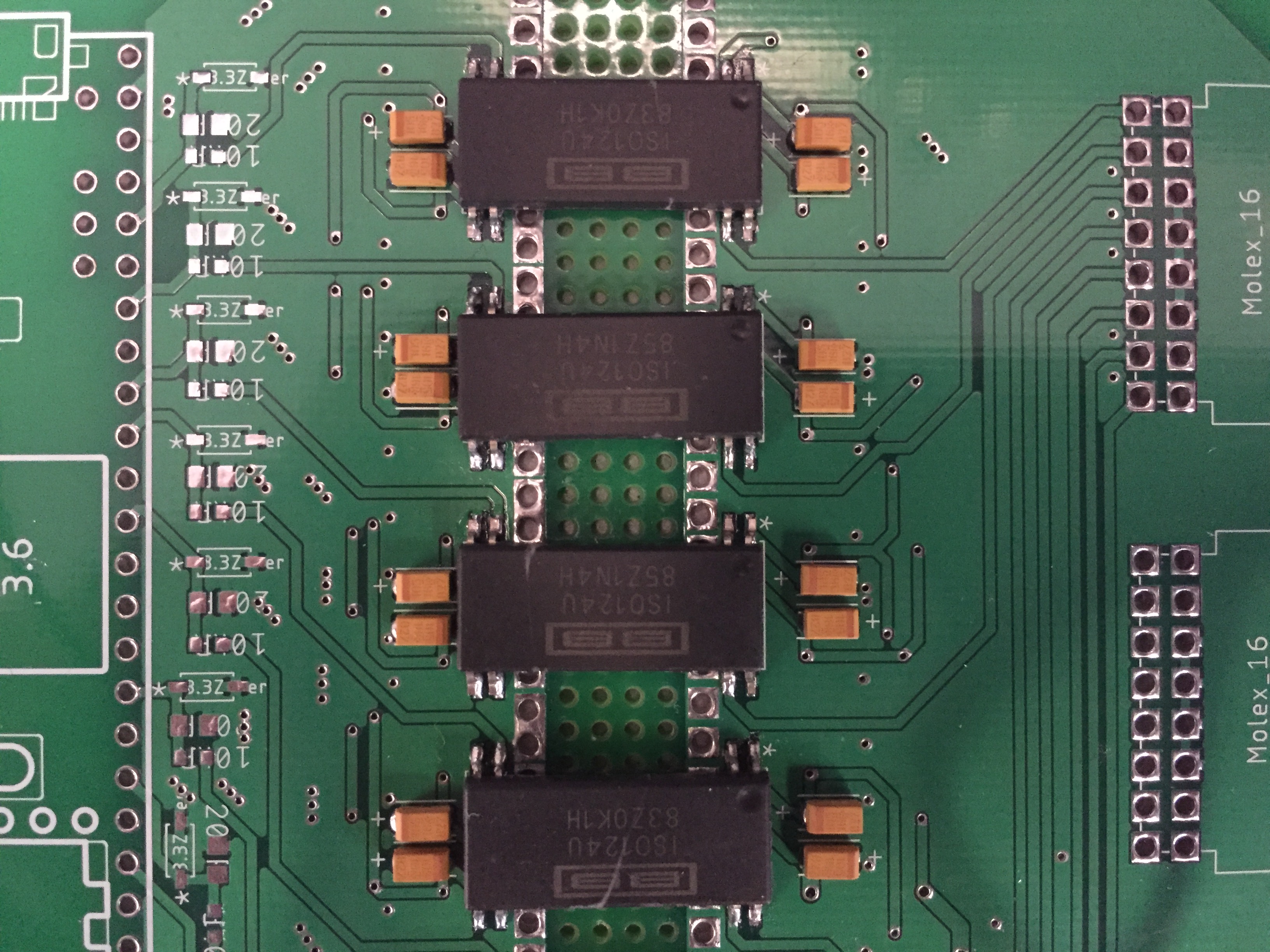
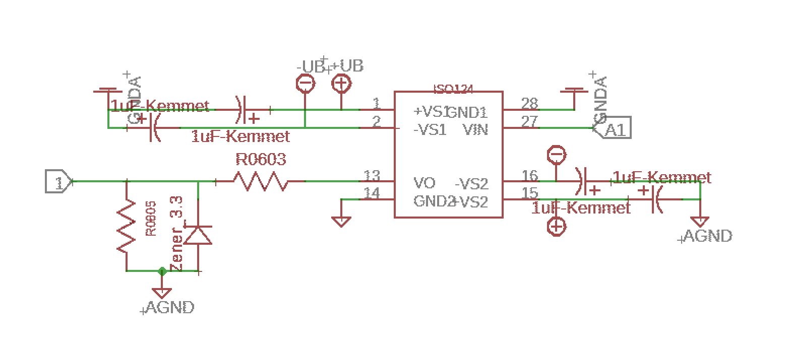
Now, I have done more tests and can explain in more details here. The schematic, board, and actual board photos are attached below. +VS1 is connected to +12V, -VS1 is connected to -12V and both are connected to ground via 1uF capacitors. We set the same at the output with isolated power supply. The input signal is connected to High-side analog input and the output signal is read from Low-side analog output, then we use a resistive voltage divider to scale down the voltage, the resistors are 10k and 20k Ohm. We do not connect the resistors at the output for testing to not pull any current from the IC at the first. I just connect the high side and low side supplies. Once the ICs are powered they start getting hot and after about 5 minutes temperature goes high to about 40 degree C. I tested different things but I could not find the main reason. 

There is one issue that may be the problem. To solder the ICs to the PCB we use heat gun or soldering iron, that heated up the IC to above 200 degree C. The storage temperature of the IC sould be between -40 to 125 degree C. Could that high temperature damage the IC and cause the abnormal temperature of the IC during the normal operation?

Thanks for all your considerations.

Best,

Hossein

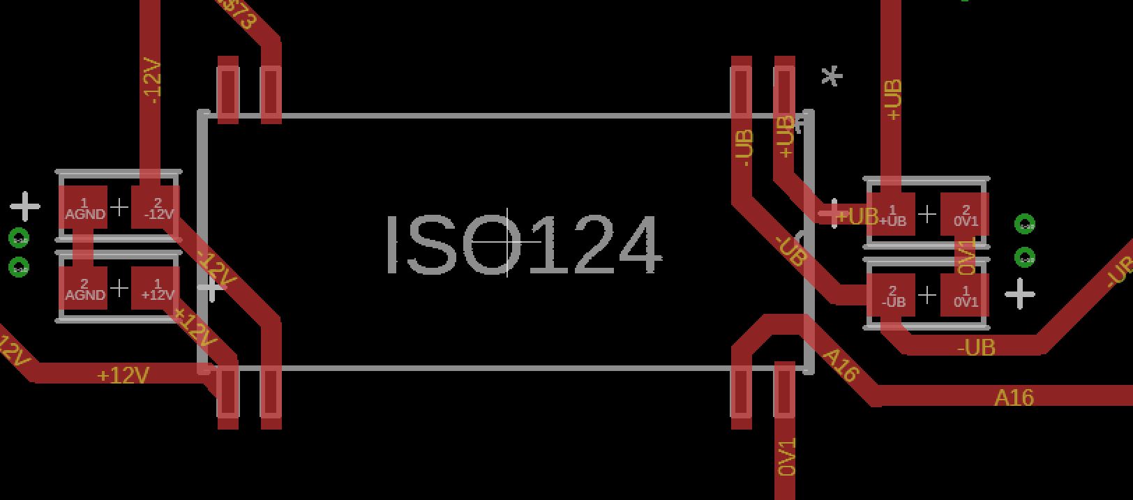
I have added some holes under the ICs location to improve heat dissipation. 

  • Hi Hossein,

    What voltage are you applying at AIN?  How are the ground pins (14 and 28) of the ISO124 referenced back to their respective GND potentials?  It's not obvious in the layout, but it looks like you might tie grounds to the copper through thermals.  Are all AGND and 0Vx tied together under the board?  One of your tantalum caps looks reversed in the layout picture (left most DUT).

  • Hi,

    Thanks for your help, regarding your questions:

    1. The voltage that will be applied to AIN is an analog signal between 0 and 5, but for this test I have not applied any voltage to AIN and it is left open for now. 

    2. There are ground planes at input and output sides and PIN 28 and 14 are connected to ground planes at the input and output sides. Those ground planes are not connected. I have attached a photo below that shows the ground plane connection at one side of the IC. I could not understand this sentence "you might tie grounds to the copper through thermals". However, I have tried to clarify the ground connection here. 

    3. As I checked the Caps, they are all in the correct direction. 

    About the soldering method, could that be the reason behind this issue? Could the heat during soldering the IC to the board (200 to 300 degree C) damage the IC and cause the abnormal temperature of the IC during the normal operation?

    Appreciate all your help.

    Hossein

  • Hi Hossein,

    letting the input pin float is no good idea at all. Connect it to input signal ground during the testing.

    Kai