This thread has been locked.

If you have a related question, please click the "Ask a related question" button in the top right corner. The newly created question will be automatically linked to this question.

OPA544: Simulated VS acutal howland current source

Part Number: OPA544
Other Parts Discussed in Thread: TINA-TI,

Hi Everyone, 

I have been having trouble with the this for some time now. 

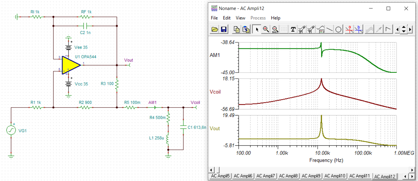
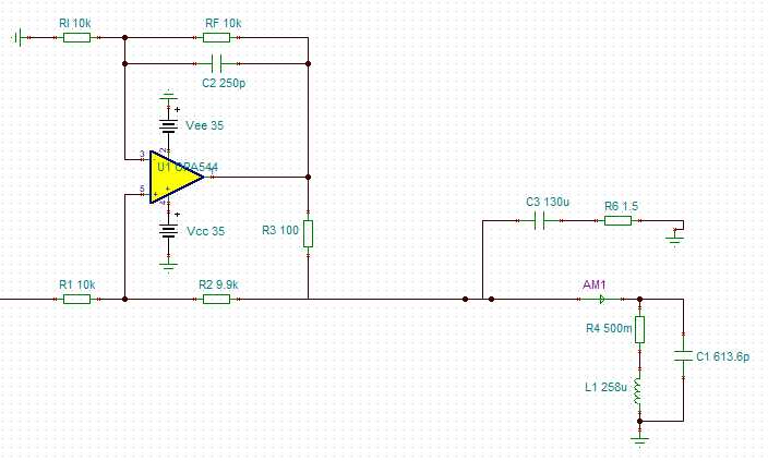
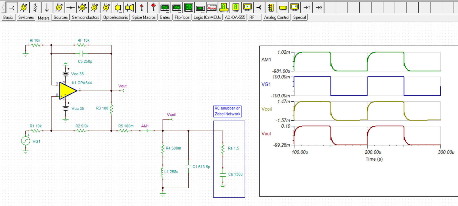
I wish to use a Howland current source to drive a constant AC current of bandwidth 10KHz into a coil. I have measured the coil parameters on an LCR meter, these are shown in the spice model below. I am aiming for a current of ~100mA's magnitude.

And then the actual transfer function measured using an impedance analyser:


What could be happening here? I have tried everything to increase the bandwidth of my circuit but it always remains the same (changing the feedback capacitor and the network resistors). I don't know whether to try and scrap the Howland and go for another bi-directional current source, but that would be irritating because I have all the components I need for the Howland. 

Any help would be greatly appreciated. 

kind regards,

Joel. 

  • Hi Joel,

    are you sure that your LCR meter is working correctly?

    Kai

  • Hi Joel,

    Thanks for your post. Please accept delayed response as many of us are on holiday break. We will support you shortly.

    -Tamara

  • Hi Joel,

    with TINA-TI I get this:

    joel_opa544.TSC

    Take care, at the resonance frequency the coil becomes very high ohmic. As consequence the output of OPA544 can go into saturation and might no longer be able to deliver the desired load current.

    Kai

  • Hi Kai,

    Thanks very much for doing this. Indeed the resonant frequency of the coil would be an issue, this is actually in the ~100KHz, I notice you have used a capacitance value several orders of magnitude larger than my coil parameters. 

    On a more practical note, is there anything that would cause differences in this simulated circuit and an actual implementation in terms of bandwidth reduction? I can't get my head around why my implemented circuit has a much smaller bandwidth. 

    Kind regards and happy new year to you all, 

    Joel. 

  • Hi Kai,

    I should have said in my last reply, the LCR meter is good, it is frequently used in our lab to test a wide variety of coils, it's an Agilent 4284A. 

    Kind regards,

    Joel. 

  • Hi Joel,

    I'm sorry, the numbers in your picture are soo tiny...

    Again, as I have already mentioned, keep in mind that at the resonance frequency (and already way below !) the impedance of coil is heavily increasing and that the output of OPA544 might go into saturation. So, the simulated frequency response might only be valid for small enough input signals.

    What is your exact input signal? Frequency, shape, amplitude? And, very important, what is the supply voltage of your OPA544?

    Kai 

  • Hi Kai, 

    I should have made the value a little clearer, apologies for that. 

    I am inputting a 17 Volt Gaussian waveform with a bandwidth of roughly 10KHz, the circuit is supplied with 32 volts. 

    regards,

    Joel. 

  • Hi Joel,

    I forgot to wish you a Happy New Year!!

    What input signal have you used in the LTSpice simulation?

    Can you show a picture of the Gaussian pulse (pulse versus time)?

    Kai

  • Hi Joel,

    Please provide us a larger image of the OPA544 circuit so that we can know for certain the component connections and their values. I do think that Kai is on to the cause of the frequency peaking, but it is difficult to do meaningful calculations and simulations without having the circuit details.

    Thanks, Thomas

    Precision Amplifiers Applications Engineering

  • Hi Thomas, Kai

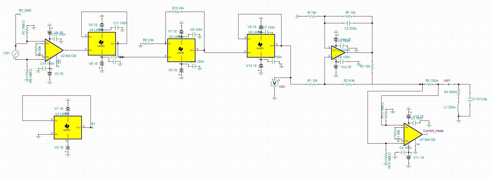
    I have added an amended version of Kai's circuit with the values that I have along with some changes to the Howland resistor and capacitor values. This is a more complete version of the actual circuit. To clarify a few details and to provide a clearer picture of what I'm doing, a Gaussian signal is sent from another device which is then referenced to the board ground, buffered and amplified. This signal is fed into a Howland current source and a current then injected into an inductive load (a coil). There is a second reflection coil not added in the simulation, in which the induced voltage is measured again with a differential amplifier. The transimpedance of the coil is then measured from the current and voltage measurements. 

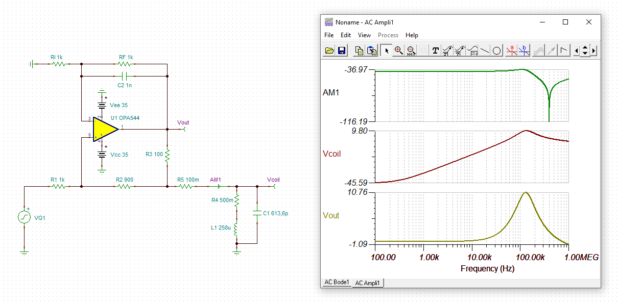
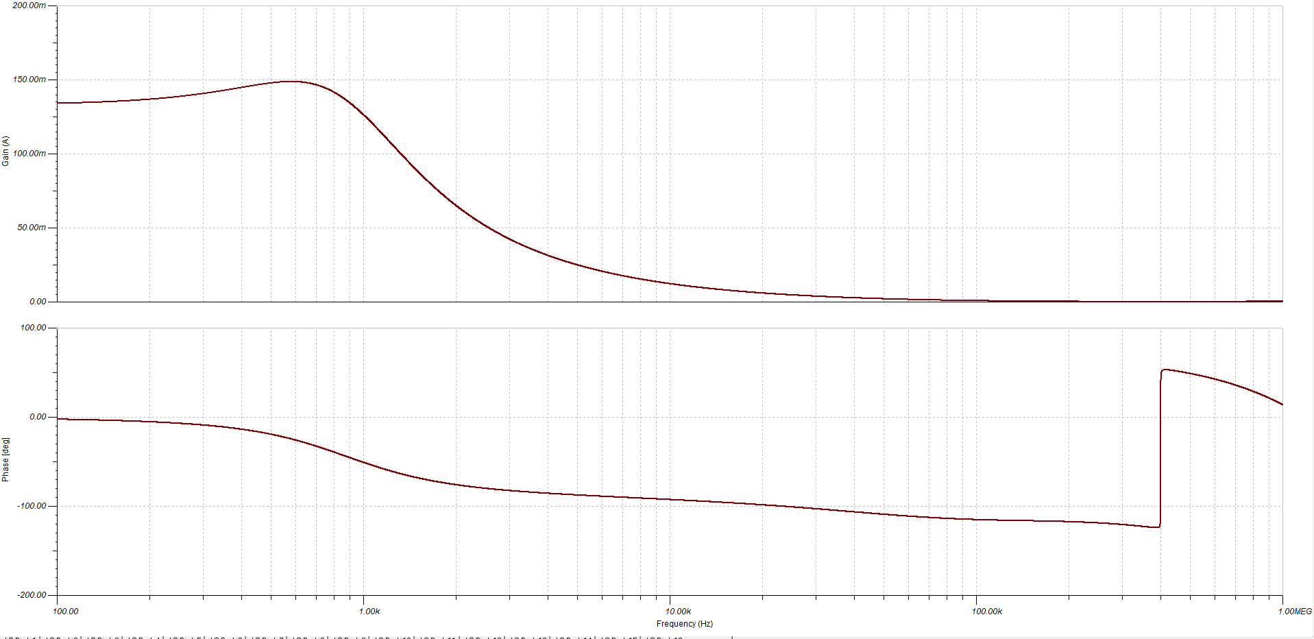
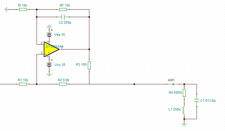
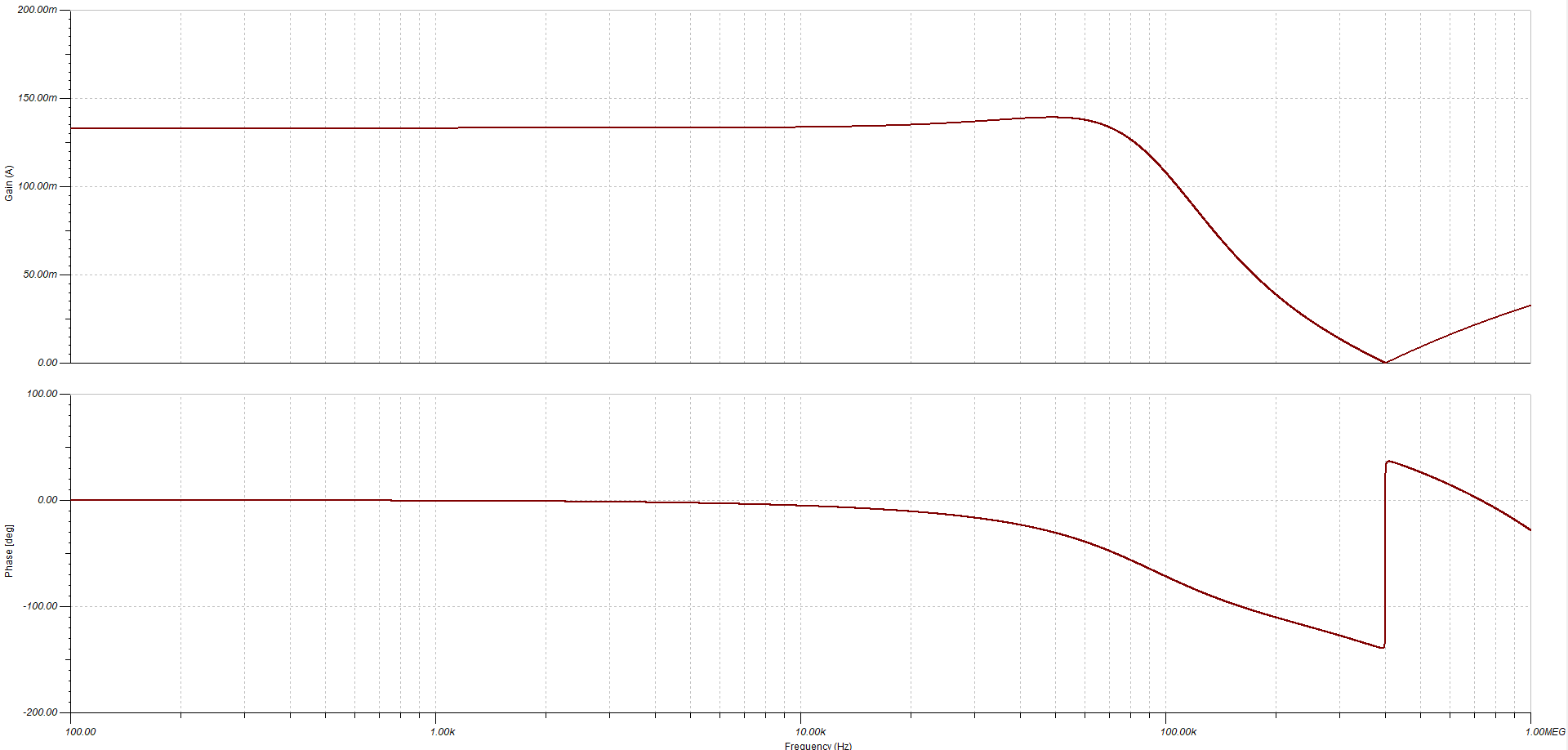
    The simulated source voltage is just a sinusoid with an amplitude of 1volt, the gain has now been changed to 14.307 (including the initial IA gain). As mentioned previously, I am interested in a bandwidth of 10KHz. I have followed the advice of the following documents http://www.ti.com/lit/an/snoa474a/snoa474a.pdf and https://www.analog.com/media/en/training-seminars/design-handbooks/designers-guide-instrument-amps-complete.pdf, but if you have any further advice then it would be greatly appreciated. I previously thought that the peaking was owed to the Howland instability, but having looked at the AC sweep of the current there is a peak at the resonant point of the coil:

    Current (AM1) with inductor and capacitor:

    Current (AM1) without inductor and capacitor:

    This is OK though because it can be dampened with the addition of the feedback capacitor. However, my original problem was that the bandwidth (-3dB point) of the circuit is significantly less than the simulated. This could be because the circuit was implemented incorrectly or PCB layout problems. I suppose I am asking for anything that should be considered when practically implenting this circuit that you can think of? 

    If there is anymore information you need please let me know. 

    kind regards,

    Joel. 
    Edit: Kai, what did you mean by 'the simulated frequency response might only be valid for small enough input signals'? Is this referring to the circuits gain-bandwidth product?

  • Hi Joel,

    All indications from the first gain/phase plots are that the OPA544 Howland Pump load is the behavior of a parallel resonant circuit. The second set of plots, without the reactive loads in place exhibits a second-order response having gain peaking.

    I have ran some stability analysis scenarios on the circuit first with the reactive load, second with the reactive load and added an RC snubber (Zobel network) across the load, and third added an load isolation resistor to the snubber and complex load circuit. I included the results in the attached WORD file.

    The results don't line up exactly with your measured results, but I do think the simulation results support that the OPA544 Howland Pump circuit can be compensated in to reduce the gain peaking observed at high frequencies.

    Regards, Thomas

    Precision Amplifiers Applications Engineering

    OPA544 Howland Current Pump complex load.docx

  • Hi Joel,

    your attachment got lost somehow. From the automatic email notification I extract this file:

    joel_opa544_1.TSC

    Is this your latest update of the circuit?

    Kai

  • Hi Thomas,

    I will take a look at that, thanks. 

    Kai, sorry about that I thought I has attached the document, hopefully it shows now?

    regards,

    Joel. 6278.joel_opa544_ammended.TSC

  • Hi Thomas,

    Thank you for your help, the Zobel network is a great idea. I have a question though, what is the isolation resistor for?  

    Joel. 

  • Hi Joel,

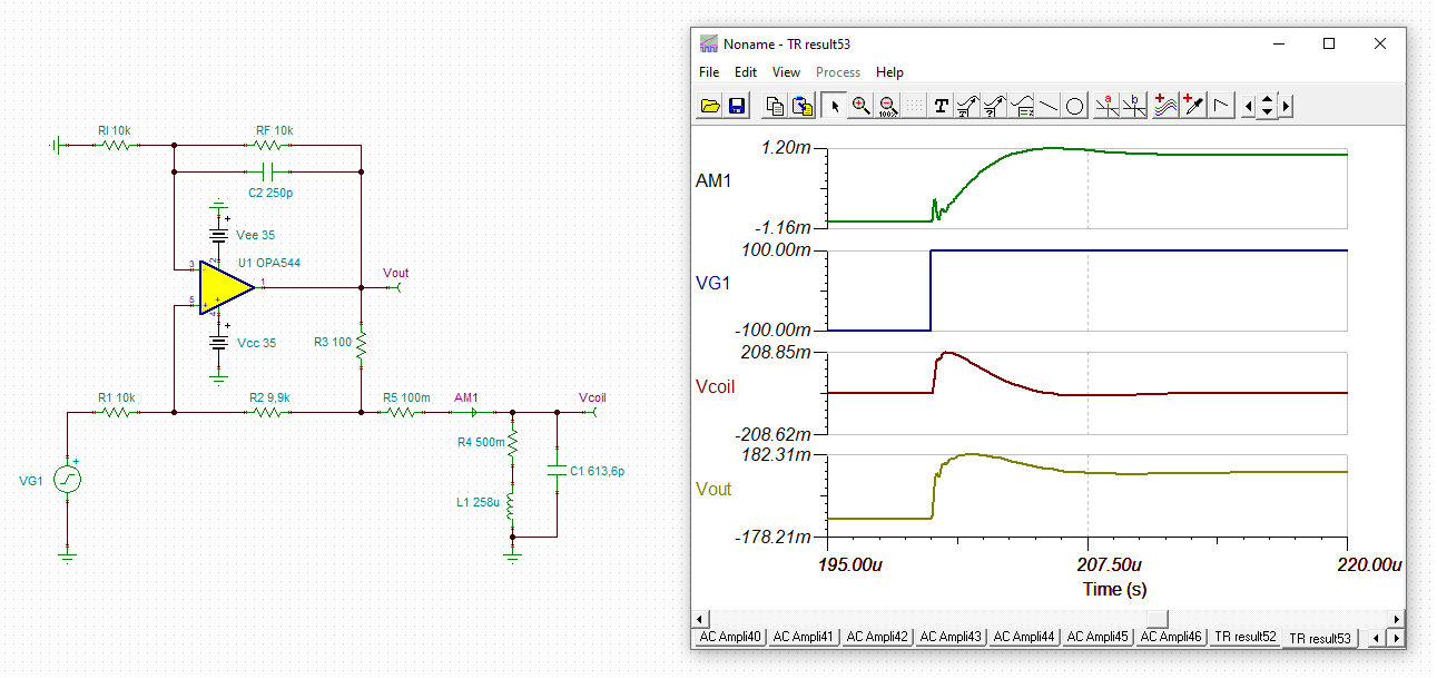
    your decision to increase the feedback resistors, especially R3 (in my schematic), is a very good idea to improve the stabilty. And you have found a very good compromise with C2=250pF. C2=270pF would also be a good choice.

    I show some results of the TINA-TI simulation now.

    Frequency response:

    Small signal transient response:

    With zoom:

    The ringing at the edges comes from the self-resonance of your coil.

    The large signal transient response:

    The transient response with 10Vp sine input signal at 1kHz:

    The transient response with 10Vp sine input signal at 10kHz:

    And the transient response with 10Vp sine input signal at 100kHz:

    And the TINA-TI file:

    1172.joel_opa544_a.TSC

    Kai

  • Hi Joel,

    The Zobel network does the majority of the compensation. There is a high frequency second pole that looks to get pushed out a little higher in frequency when the isolation resistor is included. Including the resistance helps increase the phase margin. 

    I was reviewing the correspondence that you and Kai have been exchanging showing the results of scaling the resistors higher and changing the feedback capacitor. I changed the OPA544 circuit where the Zobel network was used to see what its small step response looked like with the component changes. This is the simulation result I received:

    The Zobel network is the same as previously described and some optimization might be desired with regard to the new 250 pF feedback capacitor value. The waveforms certainly look more heavily damped so I wouldn't expect much peaking to occur in the frequency response curve.

    Regards, Thomas

    Precision Amplifiers Applications Engineering

    OPA544_ tranz_01.TSC

  • Hi Thomas, 

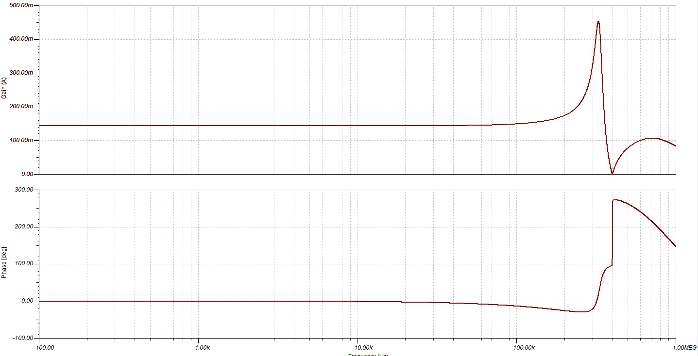
    Thanks for the reply. The only problem with including the snubber circuit is that it massively reduces the bandwidth of the current to be injected in the coil itself:

    Without:

    It appears there is a trade off with circuit stability and for my coil current bandwidth. 

    I think this issue can now be called resolved. Thanks to both of your for the discussion it has been very useful. 

    All the best, 

    Joel. 

  • Hi Joel,

    two final points:

    To decrease the heat dissipation within the OPA544 you can choose a lower supply voltage for the OPA544. +/-25V should be ok.

    Also, I think there is no need for U4 and U6 in your circuit. Or am I wrong? Can you tell me the reason for U4 and U6?

    Kai

  • Hi Kai,

    I buffer outputs out of habit. U4 isn't needed since the IA is used to measure the input voltage. U6 is there to prevent the Howland from loading the non-inverting amplifier. 

    regards,

    Joel. 

  • Hi Joel,

    I think there's no need for U4 and U6. U5 is capable of driving the Howland current source by itself.

    Kai