This thread has been locked.

If you have a related question, please click the "Ask a related question" button in the top right corner. The newly created question will be automatically linked to this question.

DRV 8825 EVM USB Opcode for DIR

Other Parts Discussed in Thread: DRV8825, DRV8825EVM, MSP430F1612, DRV8812

I wish to control the EVM board on a Linux system.

First, is there any example code to control the board over Linux?

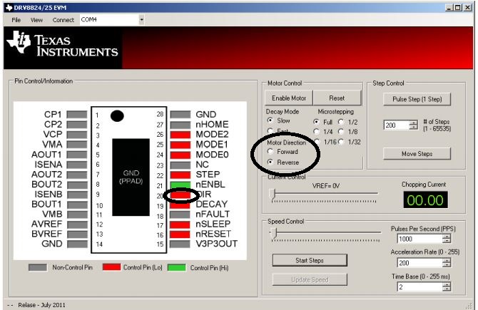
If not, AppDeff.h in the firmware gives the opcodes, which I believe I send to the USB port. What is the boards port?  Or is it assigned at runtime? I can see START_STEPPER, STOP_STEPPER< STEPPER_SPEED, and MOVE_STEPS. I do not see DIR.  Do I set that using the GPIO? 


The DRV8825 is fed through P4.4/TB4. Do I sues TBCCTL4 as a GPIO?

Thanks

Ralph

  • Hi Ralph,

    There is no example code to control the board over Linux.

    The board port is assigned when it is plugged in.

    DIR is set using a GPIO.

    I don't recall if TBCCTL4 is used, but the mcu source code for the EVM is available online. Look in the hardware zip file in the DRV8825EVM folder.
  • Hi Rick
    It appears that the USP Opcode to set/unset P4.4 is what I need.
    Let me approach my problem from a different direction. The DRV8824-25 tab on the Windows GUI app has a 'window' with check boxes for Control Signals. DIR is one of them. How do I set/reset DIR?

    Thanks
    Ralph
  • Hi Ralph,

    Once the GUI is communicating with the EVM, there are two methods to set/reset DIR.

    You can select the Motor Direction, Forward or Reverse button or you can click the DIR pin. Either will change the GPIO.

    When either method is activated, the GUI will send a USB command to the FTDI device, which in turn sends a UART command to the MSP430 on the EVM.

    Unfortunately, I do not know the USB command nor do I have access to the GUI source code.

    One method to determine the code is to use a USB sniffer. Once captured, the USB traffic could be sorted through to determine the command.

    Sorry I don't have the actual command available.

  • Hi Rick.
    OK.I will try a sniffer.

    I have been going through the source code and can't find it. I believe I will find how it is implemented in Task0.cpp. Case(MICRO_STEP_8812) has MS_Direction which apears to be set by masking BIT1 of SerialBuffer[3]. Case(MICRO_STEP_8824) tests if SerialBuffer[3] is true and sets or toggls TBCCTL5. (Port P4.5). This is shown as PHB/NC/BIN2 on the MSP430F1612, which coorsponds to pin 23 on the DRV8825, which is NC. While I don't understand that action, I am pretty sure that does not control the DIR line. From the DRV8812 code, I believe that the "sub-opcode" is in SerialBuffer[3]
    Thanks
    Ralph
  • For what its worth:

    The control messages are 5 bytes long. The OpCode is the first byte.

    The OpCode 0x03 corresponds to WRITE_GPIO in the MPS430 firmware for the DRV8825 EVM.  

    DIR is sent as 03 10 00 00 00

    clearing DIR is sent as 03 00 00 00 00

    I'm calling the 10 the control code. The control codes for WRITE_GPIO are

    DIR 03

    DECAY 02

    nRESET 40

    nSLEEP 80

    clear codes 00

    The source will have to keep track of the codes sent because they combine. For example DIR + DECAY +nSLEEP is 92

    MODE OpCode is 16, which corrosponds to SPI_GPIO, with the control codes 

    MODE0 08

    MODE1 02

    MODE2 01

    nENABLE has the OpCod 0E, which corresponds with SET_TMR_OUT , with the control code 02.

    Lines 30 to 35 (plus a comment that I added at line 32) in Task0.cpp

    30 // Write GPIO Data [ OPCODE = 3 ] [ GPIO DATA ] [ Not Used ] [ Not Used ] [ Not Used ]
    31 // GPIO DATA = P47/ P46/P45/P44/ NO/ NO/ P41/NO
          // (DRV8825) nSLEEP/nRESET/ NC/DIR/STEP/nENABLE/nDECAY/NO
    32 case (WRITE_GPIO):
    33 P4OUT = SerialBuffer[1]; //set bit pattern to contents of SerialBuffer[1]
    34 SerialOutBuffer[1] = ~SerialBuffer[1];
    35 break;


    I will add another reply if I run into something that is not obvious in Task0 that needs explaining.