This thread has been locked.

If you have a related question, please click the "Ask a related question" button in the top right corner. The newly created question will be automatically linked to this question.

TIDA-00961: some question about schematic

Part Number: TIDA-00961

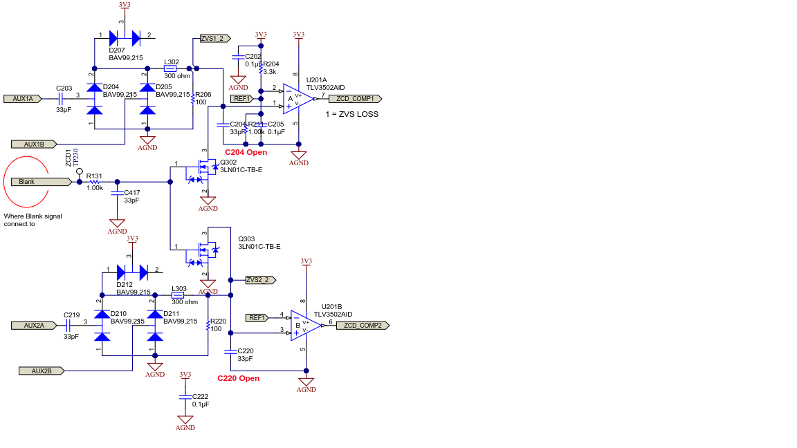
A. I think maximum inductor voltage is 390V(Vo),and the turn ratio is 6:1,so the secondary side maximum voltage is 65V.Why a high voltage(65V) direct connect to circuit as shown below without divide?
B. Why need to add C203、C219 in the circuit?

Thank!!!

  • Hello Chen wei lun,

    You are right that the voltage at AUX1A, AUX1B, AUX2A and AUX2B is high (~60-65V) but since we are using a very low value capacitor (C203 and C219 - 33pF), the voltage amplitude seen after the capacitor would be reduced based on the impedance it offers at the operating frequency (also very high).

    These capacitors and the resistor connected in series are also acting as a differentiator which we are using for sensing zero voltage switching through a patented technology.

    Thank you,

    Neha Nain

  • Hello Neha Nain,

    Thanks for your reply before.

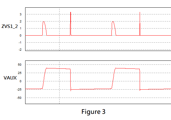
    Q1:That I think ZVS1_2 should be a square wave divide from VAUX ,but through my simulation,I can't see the waveform what I expected as shown in Figure 3.

    Those are simulation condition,Figure 1 is simulat circuit and Figure 2 is VAUX(AUX2A、AUX2B) detected circuit

    Vin = 180 (Vac)
    Vo = 400 (V)
    Io = 2 (A)
    fs = 450k~1MHz

    Q2:May I know the patented number?

  • Hi,

    As replied for another similar question, the circuit is only a simple differentator. So should be able to see the waveforms in figure 3.

    Regards,

    Salil