This thread has been locked.

If you have a related question, please click the "Ask a related question" button in the top right corner. The newly created question will be automatically linked to this question.

NE5532: Superbal circuit

Part Number: NE5532
Other Parts Discussed in Thread: RC4558

Hi team


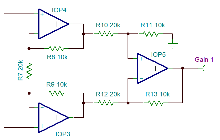
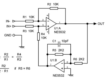
We can see that there is a super balanced circuit built with ne5532 in professional audio equipment.

  1. It is said that this circuit can keep the impedance of the two input ports equal to ensure that the CMRR is high enough and reduce the noise to a certain extent.
  2. Can you help to analyze the mechanism of this circuit to reduce noise and improve CMRR?
  3. Are there any other disadvantages of this circuit?
  4. It would be better if you could share the application note of the feedback circuit built by two op amps like this.


Best Regards

Wesley Huang

  • Wesley,

    This does make the input appear the same impedance to common mode.  Both IN- and IN+ see 20k to ground for common mode. As input common mode changes, the op amp VCM is 1/2 of the input VCM.  The gain is 1/2 (not 1 from a conventional diff amp with all resistors the same); For a difference input voltage the resistance is still 20k and equal and opposite input current flows.

    This will not reduce signal to noise ratio because gain is 1/2 (less signal) and second op amp will add noise too. Limiting the bandwidth with a matching caps across R2 and R4 with help with total noise 

    As an alternative, you could buffer both inputs with two amp amps (high impedance for both, add a real resistor to set the impedance) then combine them with a third op amp.

     Here is a TI-Tina circuit of your circuit (with my caps)

    SuperBalance.TSC

  • Hi Ron,

    Thanks for your reply.

    Compared with the traditional differential amplifier structure with R4 grounded, what are the advantages of this circuit? Because it seems that the traditional differential amplifier structure can keep the same impedance of in - and in +.

    Best Regards

    Wesley Huang

  • Wesley,

    For the single amp input (R4 ground) the input impedance for common mode is 20k just like the super bal. However, for an input difference. IN+ doesn't get the same termination voltage as the super bal. So current for IN+ won't be in scale with IN- That is the difference.

    Another way is a 3 amp diff amp that has high impedance inputs that can be used as is or you could add resistors to ground to make any input impedance that is desired.

    IN+ is top left , IN- goes to bottom left

  • Hi Ron,

    Thanks for your reply.

     Why the IN+ doesn't get the same termination voltage as the super bal ? Could you please kindly explain that?

     How does this benefit the CMRR?

    Best Regards

    Wesley Huang

  • Wesley,

    Moving R4 connection from ground to an inverted output does make a difference when the output is not zero.

    Tomorrow , I'll sim all three circuits and see what the results say about CMRR 

  • Hi Ron,

    Thanks for your reply.

    Looking forward to your simulation.

    Appreciate that!

    Best Regards

    Wesley Huang

  • Wesley,

    I simulated with a RC4558 because I don't have a NE5532 model.

    Below are the results for CMRR and noise. Noise was totalled from 1Hz to 10kHz.

    The last two columns compared the results to the forward gain.  

    Circuit CMRR Noise BW 10kHz Signal Gain CMRR S/N Noise S/N
    SuperBal 102dB 2.2uV -6dB 96dB 4.4uV
    Diff Amp 96dB 3.6uV 0dB 96dB 3.6uV
    3 AMP 102dB 3.7uV 0dB 102dB 3.7uV