This thread has been locked.
If you have a related question, please click the "Ask a related question" button in the top right corner. The newly created question will be automatically linked to this question.
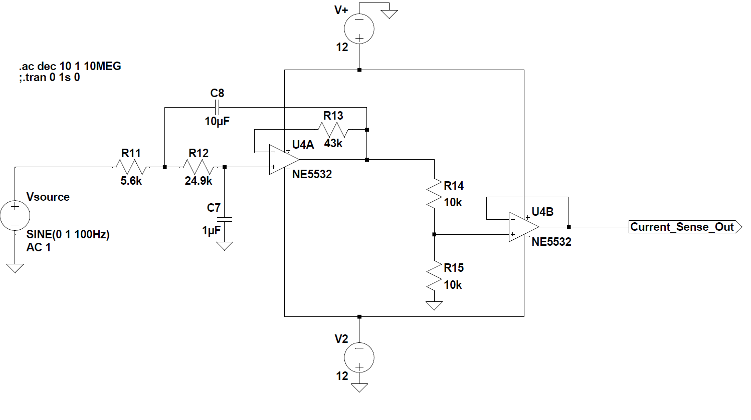
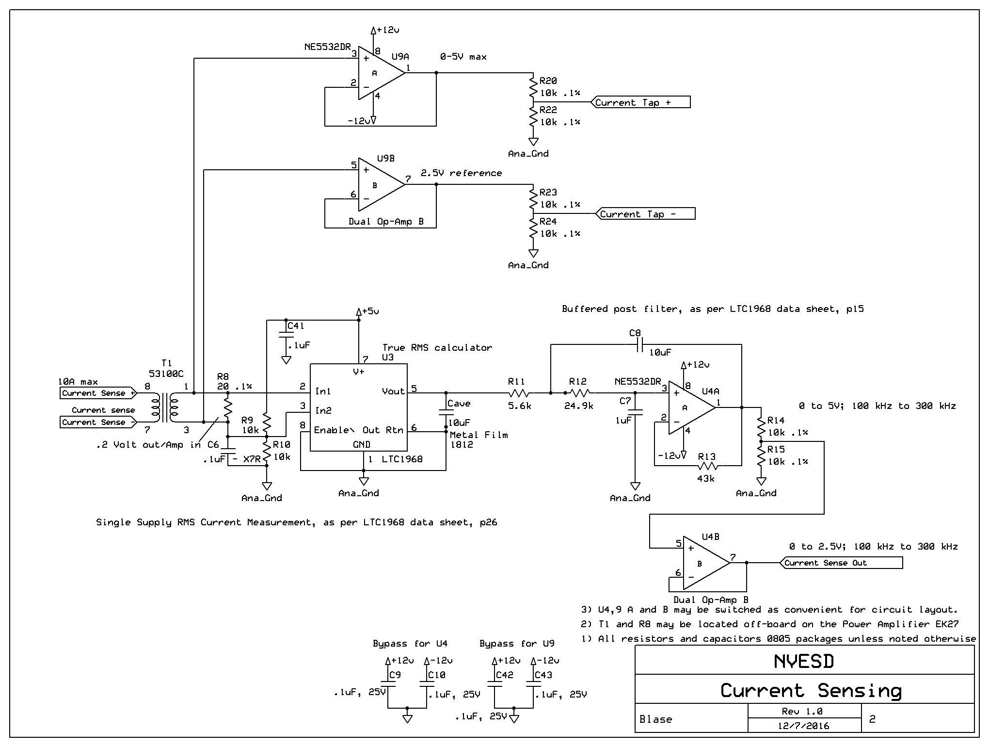
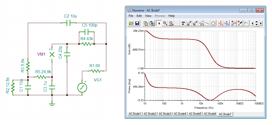
Following the directions in the datasheet for the Linear LTC1968, I implemented a Sallen-Key filter with buffer as per the attached schematic.
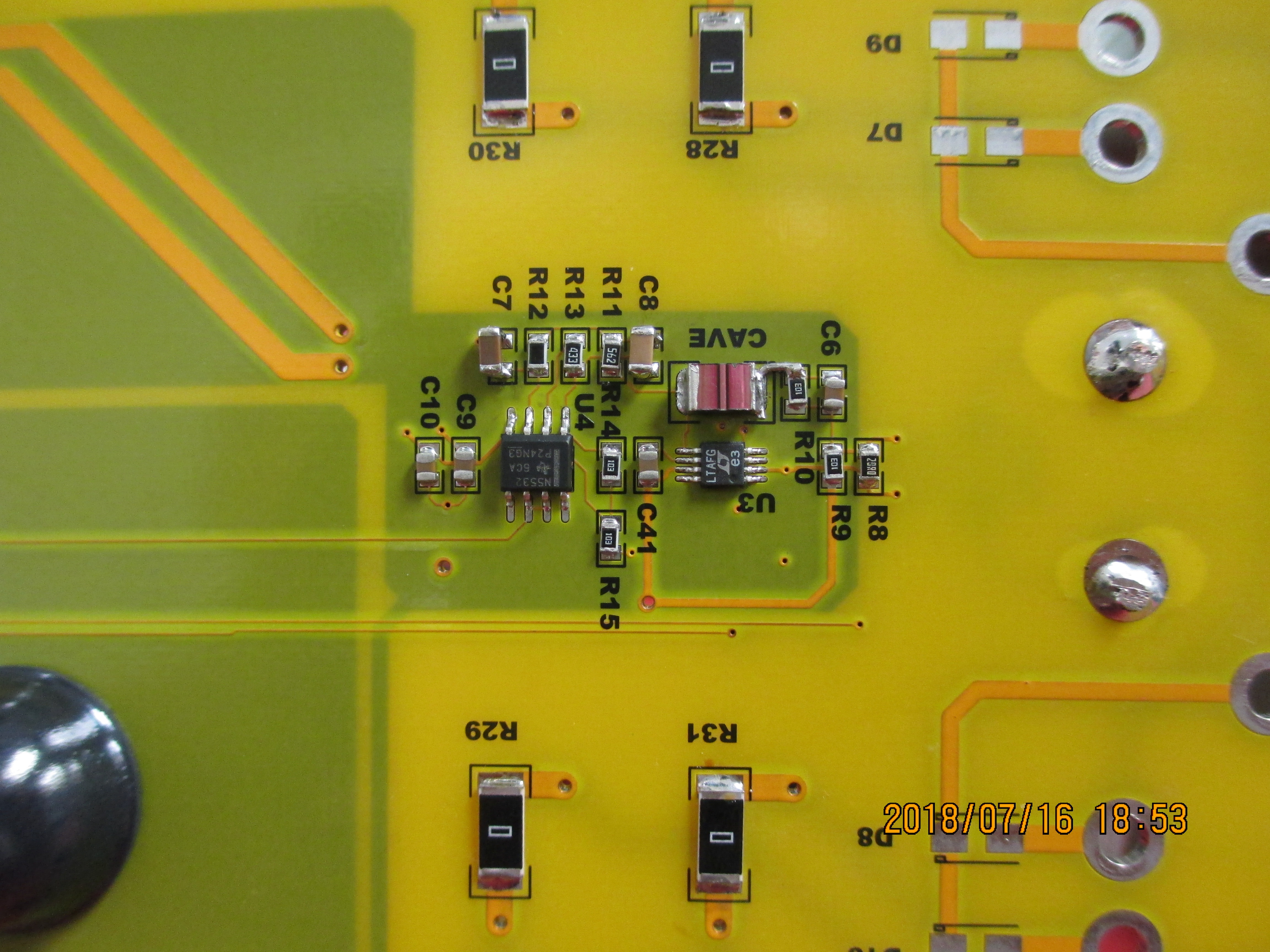
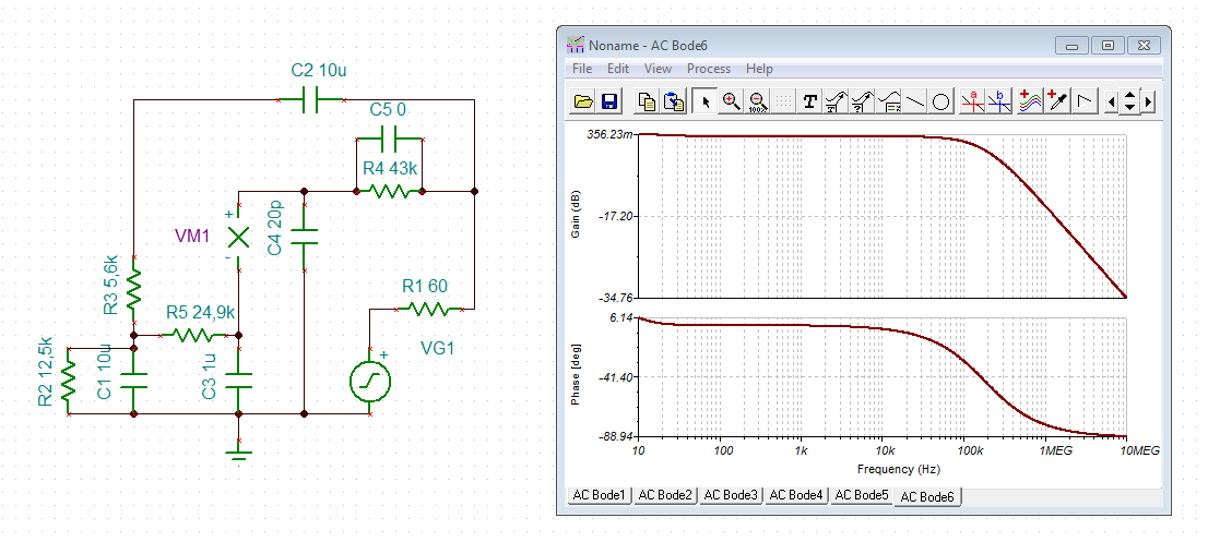
When I model the circuit in LTSpice, it works fine and is stable. On the PCB, however, it nicely oscillates with a 400 kHz, 1V p-p sine wave. I've tried and I can't make it do that in LTSpice. It's obviously a layout problem, but any suggestions on where to look and how to fix would be greatly appreciated. On the board, all components are SMT. What I did notice is that R11, R12, and R13 are set close together, and putting a finger close to them affects the oscillation, usually increasing it, so it's probably capacitive coupling somewhere.
Hi Paul,
R13 is the scapegoat! It introduces a phase lag and erodes the phase margin of NE5532. You could omit R13. Or connect a 100p cap in parallel to R13.
Hhm, the NE5532 has a big input bias current which will produce some avoidable offset voltage at output of circuit. Is there a special reason why you use the NE5532? TI has better suited OPAmps...
Kai
that did it! Thanks. A clear case of following an example (the LTC1968 example) without paying attention to what's actually there.
I do kind of wonder why the LTSpice model doesn't oscillate though.
I used the NE5532 because I had some in stock. Any recommendations?
Hi Paul,
if you can live with the offset voltage then you can use the NE5532, of course, and everything is fine. :-)
That's the big problem with these simulations, you never know what's actually going on... Because of this, I allways carry out simplified phase stability analysis which only contain the open loop output impedance and input capacitance of OPAmp:
Kai