This thread has been locked.

If you have a related question, please click the "Ask a related question" button in the top right corner. The newly created question will be automatically linked to this question.

TAS5806MD: Measure THD+N on Output

Part Number: TAS5806MD

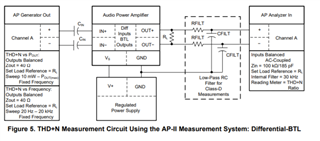
I try to measure the output from my circuit board. Therefore i am using an Agilent MSOX 2004A and a MATLAB programm. The thing is that I sill have a lot of switching frequencies remaining in the outputsignal.  I read the document "SLOA068A Guidelines for Measuring Audio Power Amplifier Performance" and tried the RC filter on Page 8 in Figure 5, but that only set the amplifier in HiZ mode, as long as i connected the ground of the am to the ground of the RC Lowpass.
Whats funny is, that this RC filter worked just fine for my TPA3129 board, but doesnt for my TAS5806MD board.

How do i correctly lowpass the switching frequencies in order to measure the output?

  • Hello Severin,

    Can you readback the fault registers for the TAS5806MD.

    The TPA3129 and TA5806MD have differences in their output stage, can you try changing the ferrite bead filter with a L-C filter to see if you are seeing the same issue with the Hi-Z.

    Best regards,

    Luis

  • Hello Luis,

    I will try to readback the fault registers tomorrow.
    I tried with the L-C filter and it seems to work fine, but still the switching frequencies are pretty dominant so there must be a way to filter those signals in order to optain a good waveform. My scope can't capture enough points to read the PWM output and then lowpassfilter the data in MATLAB, I already tired it without success, so I assume a hardware solution is needed. Do you have any suggestions? How would you measure THD+N with an oscilloscope?

    Best regards,

    Severin

  • Hello Luis,

    here are the Values of the registers in decimal:
    CHAN_FAULT_REGISTER = 0
    GLOBAL_FAULT1_REGISTER = 0
    GLOBAL_FAULT2_REGISTER = 0

    So no errors displayed in the registers. Does anyone have a suggestion why it is still not working when U ground the RC filter?

    Best regards,

    Severin

  • Hello Severin,

    for the hardware solution, you would have two options:

    1. RC filter. what is the value you used here. to get enough attenuation for the PWM frequency, a strong RC would be required. or you need to use higher order active fitler.

    2. LC filter is the most easy way. you can find the LC filter information at datasheet section 10.1.2 "Inductor Selections"

    Hope the information can help you.

    Dylan