This thread has been locked.

If you have a related question, please click the "Ask a related question" button in the top right corner. The newly created question will be automatically linked to this question.

LME49860: LME49860: Trying to understand why datasheet shows clipping behaviour roughly 8 Volts below actual clipping point?

Part Number: LME49860
Other Parts Discussed in Thread: OPA604, OPA134

I am trying to understand the LME49860 data sheet. This Opamp has a max supply voltage of+-22V which should give a max output swing of +-21.2V into 10k. Yet when I look at the data sheet, the graph shows a strong rise of distortion at about roughly +-12V - similiar to typical clipping beviour:

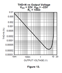
Do I missinterpret things or is this correct? If it was correct, does it mean that the opamp can withstand +-22V supply voltage, but it's headroom is similiar to a typical standard opamp running at +-15V?  I'm confused...

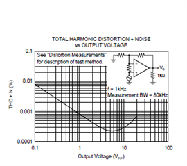
Here's the graph of the OPA604, which runs at +-24V. This makes sense to me:

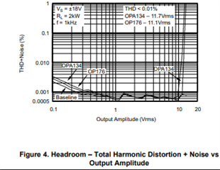
Or the OPA134, probably running at +-18V. Better that the LME49860 at +-22:

Is the LME49860 really behaving like that?

Thank you for reading,

Michael

  • Michael, looking at the plots it seems THD suffers at about +/-12V which can be an indication of clipping. Let me dig around more and will update this if I find out anything different.

    Regards,

    Arash

  • From data sheet: The LME49860 is part of the ultra-low distortion, low noise, high slew rate operational  amplifier series Line Drivers optimized and fully specified for high performance,  high fidelity applications. The LME49860 combines extremely low voltage noise density (2.7nV/√Hz) with vanishingly low THD+N (0.00003%) to easily satisfy the most demanding audio applications. To ensure that the most challenging loads are driven without compromise, the LME49860 has a high slew rate of ±20V/μs and an output current capability of ±26mA. Further, dynamic range is maximized by an output stage that drives 2kΩ loads to within 1V of either power supply voltage and to within 1.4V when driving 600Ω loads.

    Also  note that the way they are measuring the THD is different,   so probably  the THD plot should not be used to extract information about output clipping. Again from data sheet:

    DISTORTION MEASUREMENTS The vanishingly low residual distortion produced by LME49860 is below the capabilities of all commercially available equipment. This makes distortion measurements just slightly more difficult than simply connecting a distortion meter to the amplifier’s inputs and outputs. The solution, however, is quite simple: an additional resistor. Adding this resistor extends the resolution of the distortion measurement equipment. The LME49860’s low residual distortion is an input referred internal error. As shown in Figure 109, adding the 10Ω resistor connected between the amplifier’s inverting and non-inverting inputs changes the amplifier’s noise gain. The result is that the error signal (distortion) is amplified by a factor of 101. Although the amplifier’s closedloop gain is unaltered, the feedback available to correct distortion errors is reduced by 101, which means that measurement resolution increases by 101. 

    Regards,

    Arash

  • Arash, thank you for your replies. Unfortunately I still do not understand what's wrong: the chip, the diagram I refer to - or my thinking?

    looking at the plots it seems THD suffers at about +/-12V which can be an indication of clipping

    Yes, that's what I thought and described in my original post.

    To ensure that the most challenging loads are driven without compromise, the LME49860 has a high slew rate of ±20V/μs and an output current capability of ±26mA. Further, dynamic range is maximized by an output stage that drives 2kΩ loads to within 1V of either power supply voltage and to within 1.4V when driving 600Ω loads.

    The first diagram shows the distortion behaviour at +/- 22V supply voltage into a 10k load. The chip should drive that load easily to within 1V of supply power - so a swing of +/- 21V peak should be no problem under these conditions. The diagram simply states (V) - is that peak or rms? I did assume it's peak, 21V peak should be 14.85V rms, this would put things more into the ballpark. But roughly 3V are missing? It still doesn't feel right.

    Also  note that the way they are measuring the THD is different,   so probably  the THD plot should not be used to extract information about output clipping.

    I do not understand how the methodology explains the shown effect and I didn't extract information about output clipping from the plot. 

    the graph shows a strong rise of distortion at about roughly +-12V - similiar to typical clipping beviour

    Yet in my understanding the steep rise of the plot is similiar to clipping behaviour, as opposed to the slower rise of the OPA604 for example.

    I simply want to know: does the chip maintain it's probably excellent distortion behaviour reasonably close to the clipping point - or does the distortion rise already dramatically and significantly way below the clipping point (for whatever reason)? Maybe someone just messed up the diagrams and all is well - or the diagram is correct and the chip is probably great for HiFi aplications with the associated lower levels than I expect and want to be able to handle in my studio equipment?

    Regards,

    Michael

  • Hi Michael,

    I've been looking into this thoroughly and we've got an answer.

    In order to check the output voltage swing capabilities of LME49860 please refer to figures 99 to 101. These plots will show the correct/expected voltage at the output for each supply voltage level.
    Some of the other plots are not accurate on its captions. Specifically the ones that say Vcc = 22V and Vee = -22V are actually for Vcc = 17V and Vee = -17V.

    Please feel free to respond if have any further questions.

    Best regards,
    -Ivan Salazar
    Applications Engineer - Low Power Audio & Actuators