


Other Parts Discussed in Thread: PGA411-Q1, SYSCONFIG, LAUNCHXL-F28379D
-
Hellow
I am having the same issue that Vish Raman had faced in his original thread where any command request is responding with a message like 0x46. Can I know how this got resolved?
I am trying to read the Dev_Stat5 and Dev_Stat6 registers from the PGA411Q1EVM, via the external controller (F28379D) Dev Kit.
F28379D is the master
PGA411-EVM is the slave,
I am trying to read the register values via the J11 ping on the PGA411-EVM.
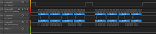
On the scope, I am confirming that the NCS, SCK, and the SDI Pins are all valid, but the SDO output is always 0x41,0X00,0XFF,0X41
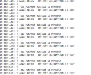
after execution of the code I am getting a hal_assert() error.
Any help is appreciated.
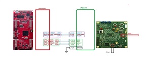
Respected code and pin connection are attached below
logic analyzer received data
pin connection master (f28379d) slave PGA411_Q1_EVM
//#############################################################################
//
// FILE: empty_bitfield_driverlib_main.c
//
// TITLE: Empty Example
//
// Empty Bit-Field & Driverlib Example
//
// This example is an empty project setup for Bit-Field and Driverlib
// development.
//
//#############################################################################
// $TI Release: F2837xD Support Library v3.10.00.00 $
// $Release Date: Tue May 26 17:13:46 IST 2020 $
// $Copyright:
// Copyright (C) 2013-2020 Texas Instruments Incorporated - http://www.ti.com/
//
// Redistribution and use in source and binary forms, with or without
// modification, are permitted provided that the following conditions
// are met:
//
// Redistributions of source code must retain the above copyright
// notice, this list of conditions and the following disclaimer.
//
// Redistributions in binary form must reproduce the above copyright
// notice, this list of conditions and the following disclaimer in the
// documentation and/or other materials provided with the
// distribution.
//
// Neither the name of Texas Instruments Incorporated nor the names of
// its contributors may be used to endorse or promote products derived
// from this software without specific prior written permission.
//
// THIS SOFTWARE IS PROVIDED BY THE COPYRIGHT HOLDERS AND CONTRIBUTORS
// "AS IS" AND ANY EXPRESS OR IMPLIED WARRANTIES, INCLUDING, BUT NOT
// LIMITED TO, THE IMPLIED WARRANTIES OF MERCHANTABILITY AND FITNESS FOR
// A PARTICULAR PURPOSE ARE DISCLAIMED. IN NO EVENT SHALL THE COPYRIGHT
// OWNER OR CONTRIBUTORS BE LIABLE FOR ANY DIRECT, INDIRECT, INCIDENTAL,
// SPECIAL, EXEMPLARY, OR CONSEQUENTIAL DAMAGES (INCLUDING, BUT NOT
// LIMITED TO, PROCUREMENT OF SUBSTITUTE GOODS OR SERVICES; LOSS OF USE,
// DATA, OR PROFITS; OR BUSINESS INTERRUPTION) HOWEVER CAUSED AND ON ANY
// THEORY OF LIABILITY, WHETHER IN CONTRACT, STRICT LIABILITY, OR TORT
// (INCLUDING NEGLIGENCE OR OTHERWISE) ARISING IN ANY WAY OUT OF THE USE
// OF THIS SOFTWARE, EVEN IF ADVISED OF THE POSSIBILITY OF SUCH DAMAGE.
// $
//#############################################################################//
// Included Files
//#include "F28x_Project.h"
#include "driverlib.h"
#include "device.h"//FROM TIDA-00796
#include <IQmathLib.h> /* IQ math library */
#include <stdio.h> /* standard input output lib */
#include <string.h> /* strings and arrays (for mcmcpy) */
#include "hal.h" /* hardware manager */
#include "pga411.h" /*PGA411-Q1 driver */#include "F2837xD_device.h"
#include "F2837xD_Examples.h"
#include "board1.h"//
// Defines
//
#define START_TIMER(x) { \
x = CpuTimer1Regs.TIM.all; \
CpuTimer1Regs.TCR.bit.TSS = 0; \
}#define STOP_TIMER(x) { \
CpuTimer1Regs.TCR.bit.TSS = 1; \
x = CpuTimer1Regs.TIM.all; \
CpuTimer1Regs.TCR.bit.TRB = 1; \
}
#define RED_LED_LOW GPIO_WritePin(RED_LED, 1) // 1 LOW 0 HIGH
#define RED_LED_HIGH GPIO_WritePin(RED_LED, 0) // 0 HIGH#define LOGIC_CHECK_LOW GPIO_WritePin(LOGIC_CHECK, 1) // 1 LOW 0 HIGH
#define LOGIC_CHECK_HIGH GPIO_WritePin(LOGIC_CHECK, 0) // 0 HIGH
//NOT VERIFIED
float start_time = 0.0;
float stop_time = 0.0;
//
float ticks, time_in_us, time, temp, temp1;char outbuf[30]; /* UART output data buffer for string conversion */
Uint16 angle1;/******************************************************************************
* INTERNAL FUNCTIONS PROTOTYPES
*****************************************************************************//* Function reads angle from the PGA411 and sends it over UART */
void main_GetAngleAndPrint(void);/* Function reads velocity from the PGA411 and sends it over UART */
void main_GetVeloAndPrint(void);/******************************************************************************
* INTERNAL FUNCTIONS
*****************************************************************************//* Function reads angle from the PGA411 and sends it over UART */
void main_GetAngleAndPrint(void)
{
// angle calculation for the PGA411-Q1 using IQmathLib library //
// _iq19 stores -4096 to 4095.999998093 with 0.000001907 resolution //
int16 angle_raw; // raw data from the PGA411-Q1 register //
_iq angle; // IQ math angle //
// float angle2;// terminal command //
hal_PutsUART("Angle [Deg]: ");// read data from the PGA411-Q1 //
angle_raw = pga411_ReadReg(DEV_STAT5);
angle_raw &= 0x1FFF; // preserve only ORDANGLE bits //
// multiply minimal step (LSB) with ORDANGLE value //
angle = _IQ19mpy(_IQ19(360.0 / 4096), _IQ19(angle_raw)); // 12b example // //ORIGINAL CODE
// angle = _IQ19mpy(_IQ19(360.0 / 1024), _IQ19(angle_raw)); // 10bit mode example //
// convert IQ variable to string //
_IQ19toa(outbuf, "%4.5f", angle);
// angle1 = (int) outbuf[0];// print-out the buffer //
hal_PutsUART(outbuf);
// terminal command //
hal_PutsUART("\t\r");
}/* Function reads velocity from the PGA411 and sends it over UART */
void main_GetVeloAndPrint(void)
{
/* velocity calculation for the PGA411-Q1 using IQmathLib library */
/* _iq14 stores -131072 to 131071.999938965 with 0.000061035 resolution */
int16 velocity_raw; /* raw data from the PGA411-Q1 register */
float velocity_float; /* temp for 2nd complement to float conversion */
_iq velocity; /* IQ math velocity */
/* terminal command */
hal_PutsUART("Velocity[RPM]: ");/* read data from the PGA411-Q1 */
velocity_raw = pga411_ReadReg(DEV_STAT6);/* convert 2nd complement to float */
if (velocity_raw & 0x0800) /* negative number ? */
{
/* convert to positive number first */
velocity_float = (((~velocity_raw) + 1) & 0x07FF);
velocity_float *= -1; /* and make float negative */
}
else
{
/* positive number, preserve only needed bits */
velocity_float = (velocity_raw & 0x07FF);
}velocity = _IQ14mpy(_IQ14(60 * 20000000 / 33554432), _IQ14(velocity_float + 1)); /* 12b example */ //ORIGINAL CODE
// velocity = _IQ14mpy(_IQ14(60 * 20000000 / 2097152), _IQ14(velocity_float + 1)); /* 10b example *//* convert IQ variable to string */
_IQ14toa(outbuf, "%7.5f", velocity);/* print-out the buffer */
hal_PutsUART(outbuf);
/* terminal command */
hal_PutsUART("\n\r");
}
//
// Main
//
void main(void)
{
//
// Initializes device clock and peripherals
//
Device_init();//
// Configures the GPIO pin as a push-pull output
//
Device_initGPIO();//
// Initializes PIE and clears PIE registers. Disables CPU interrupts.
//
Interrupt_initModule();//
// Initializes the PIE vector table with pointers to the shell Interrupt
// Service Routines (ISR).
//
Interrupt_initVectorTable();//
// Initializes board peripherals. This is generated by Sysconfig file
//
Board_init_1();// //
// //CODE END FOR UART - SEEN ON PINS 19 & 18 on LAUNCHXL-F28379D
// //
GPIO_togglePin(LED1);
DEVICE_DELAY_US(1000000);
hal_PutsUART("\r\n hal_PutsUART function is WORKING! \n\r");
GPIO_togglePin(LED1);
DEVICE_DELAY_US(1000000);
GPIO_writePin(AMODE, 0);
GPIO_WritePin(RED_LED, 1);
GPIO_WritePin(FAULT, 1);
pga411_Reset();
pga411_FaultReset();DELAY_US(100000); /* 100 ms delay */
pga411_DefaultCfg(); /* default config defined in "pga411_regs" */
DELAY_US(10000); /* 10 ms deglitch period when the exciter enables *//* endless loop */
while (1)
{hal_PutsUART("\r\n hal_PutsUART function is WORKING! \n\r");
DELAY_US(100000); /* 100 ms delay */
main_GetAngleAndPrint();
main_GetVeloAndPrint();
}}
///////////////////////////////////////////////////////////////////////////////////////////////////////////////////////////////
/////////////////////////////////////////// PGA411 INIT HADER FILE ///////////////
///////////////////////////////////////////////////////////////////////////////////////////////////////////////////////////////
/******************************************************************************
* TIDA-00796 Resolver Frontend based on PGA411-Q1
* Module: PGA411 driver
* Author: Jiri Panacek, j-panacek@ti.com
*
* Copyright 2016 Texas Instruments Incorporated. All rights reserved.
******************************************************************************/#include "pga411.h"
#include "hal.h"
#include "F2837xD_device.h"
#include "F28x_Project.h"
/******************************************************************************
* MACROS
*****************************************************************************/#define CRC_BITCOUNT 24 /* top 24 bits of Uint32 for CRC6 */
#define CRC_BYTECOUNT 3 /* top 3 B of Uint32 for CRC6 */
#define CRC_INITSEED 0x3F /* initial seed for CRC6 */
#define CRC_POLYNOM 0x5B /* CRC = X6+X4+X3+X+1 */#define SPI_DUMMY 0xF0 /* dummy SPI data for read operation */
#define EMPTY_LOOP
/******************************************************************************
* ENUMS
*****************************************************************************//******************************************************************************
* TYPEDEFS
*****************************************************************************//******************************************************************************
* VARIABLES, CONSTANTS
*****************************************************************************/volatile pga411_spi_frame_t pga411_spi_frame = {.addr = 0x00,
.dataout = 0x0000,
.reserved = 0x0,
.mcrc = 0x00
};pga411_reg_t pga411_regs[PGA411_REG_COUNT + 1] =
{
/* memory constants init */
[DEV_OVUV1] = {.read_add = 0x53, .write_add = 0x87, .def_val = 0x8B40},
[DEV_OVUV2] = {.read_add = 0x6B, .write_add = 0x26, .def_val = 0x00ED},
[DEV_OVUV3] = {.read_add = 0x65, .write_add = 0x17, .def_val = 0xFCFF},
[DEV_OVUV4] = {.read_add = 0xEC, .write_add = 0x39, .def_val = 0x07F2},
[DEV_OVUV5] = {.read_add = 0x52, .write_add = 0x75, .def_val = 0x1C00},
[DEV_OVUV6] = {.read_add = 0xE9, .write_add = 0x83, .def_val = 0x038F},
[DEV_TLOOP_CFG] = {.read_add = 0xA6, .write_add = 0x42, .def_val = 0x0514},
[DEV_AFE_CFG] = {.read_add = 0xC2, .write_add = 0x91, .def_val = 0x0005},
[DEV_PHASE_CFG] = {.read_add = 0x57, .write_add = 0x85, .def_val = 0x1400},
[DEV_CONFIG1] = {.read_add = 0xBE, .write_add = 0xEB, .def_val = 0x0002},
[DEV_CONTROL1] = {.read_add = 0x90, .write_add = 0x0D, .def_val = 0x0000},
[DEV_CONTROL2] = {.read_add = 0x63, .write_add = 0x38, .def_val = 0x0000},
[DEV_CONTROL3] = {.read_add = 0xDD, .write_add = 0xAE, .def_val = 0x0003},
[DEV_STAT1] = {.read_add = 0x81, .write_add = 0x00, .def_val = 0x0000},
[DEV_STAT2] = {.read_add = 0x4D, .write_add = 0x00, .def_val = 0x0000},
[DEV_STAT3] = {.read_add = 0x84, .write_add = 0x00, .def_val = 0x0000},
[DEV_STAT4] = {.read_add = 0x1F, .write_add = 0x00, .def_val = 0x0000},
[DEV_STAT5] = {.read_add = 0x41, .write_add = 0x00, .def_val = 0x0000},
[DEV_STAT6] = {.read_add = 0x6F, .write_add = 0x00, .def_val = 0x0000},
[DEV_STAT7] = {.read_add = 0xE1, .write_add = 0x00, .def_val = 0x0000},
[DEV_CLCRC] = {.read_add = 0x4F, .write_add = 0xFC, .def_val = 0x0000},
[DEV_CRC] = {.read_add = 0x0F, .write_add = 0xE7, .def_val = 0x0000},
[CRCCALC] = {.read_add = 0xD9, .write_add = 0xFF, .def_val = 0x0000},
[DEV_EE_CTRL1] = {.read_add = 0xE3, .write_add = 0x6E, .def_val = 0x0000},
[DEV_CRC_CTRL1] = {.read_add = 0x7A, .write_add = 0xB6, .def_val = 0x0000},
[DEV_EE_CTRL4] = {.read_add = 0xBA, .write_add = 0x56, .def_val = 0x0000},
[DEV_UNLK_CTRL1] = {.read_add = 0x64, .write_add = 0x95, .def_val = 0x0000},
/* for continuous read we need to read 28 times. This significantly helps */
[DUMMY_REG] = {.read_add = 0x53, .write_add = 0x87, .def_val = 0x0000},
};/******************************************************************************
* INTERNAL FUNCTIONS PROTOTYPES
*****************************************************************************//* calculate CRC6 for output data, function takes first 3B left aligned data */
Uint16 pga411_crc2(Uint32 datin);/* Xmit data to PGA over SPI, for reg use defined macros, return incoming frame */
pga411_spi_frame_t pga411_XmitSPI(Uint16 dir, Uint16 reg, Uint16 wdata);/******************************************************************************
* INTERNAL FUNCTIONS
*****************************************************************************//* CRC6 calculation - optimized for PGA411 */
Uint16 pga411_crc2(Uint32 datin)
{
Uint16 byte_idx, bit_idx, crc = (CRC_INITSEED << 2);/* byte by byte starting from most significant (3-2-1) */
for (byte_idx = CRC_BYTECOUNT; byte_idx >= 1; byte_idx--)
{
/* XOR-in new byte from left to right */
crc ^= ((datin >> (byte_idx << 3)) & 0x000000FF);/* bit by bit for each byte */
for (bit_idx = 0; bit_idx < 8; bit_idx++)
{
crc = crc << 1 ^ (crc & 0x80 ? (CRC_POLYNOM << 2) : 0);
}
}return (crc >> 2 & CRC_INITSEED); /*restore two bit offset */
}
/* Write default configuration to PGA */
void pga411_DefaultCfg(void)
{
int i;
/* go to diagnostic state */
pga411_State(DIAG);
/* unlock registers */
pga411_DeviceUnlock();/* first 12 registers to default */
/* note: for some u need to unlocked them first ! */
for (i = 0; i < 12; i++)
{
pga411_XmitSPI(WRITE, i, pga411_regs[i].def_val);
}/* go to normal state */
pga411_State(NORMAL);
}
/* Change state diagnostic/normal */
void pga411_State(Uint16 state)
{
Uint16 temp;/* Enter Diagnostic state */
if (state == DIAG)
{
/* read content of DEV_CONTROL3 register */
temp = pga411_ReadReg(DEV_CONTROL3);
temp |= 0x0004; /* set bit SPIDIAG */
pga411_WriteReg(DEV_CONTROL3, temp); /* finish R-M-W */
}
/* Go back to normal state */
else
{
/* read content of DEV_CONTROL1 register */
temp = pga411_ReadReg(DEV_CONTROL1);
temp |= 0x0001; /* set bit DIAGEXIT */
pga411_WriteReg(DEV_CONTROL1, temp); /* finish R-M-W */
}
}
/* Read data from defined register */
Uint16 pga411_ReadReg(Uint16 reg)
{
/* first read returns whatever */
pga411_XmitSPI(READ, reg, SPI_DUMMY);
/* second read returns requested data */
return (pga411_XmitSPI(READ, reg, SPI_DUMMY).datain);
}pga411_spi_frame_t pga411_XmitSPI(Uint16 dir, Uint16 reg, Uint16 wdata)
{
pga411_spi_frame_t out, in;/* do we read data ? */
if (dir == READ) { out.addr = pga411_regs[reg].read_add; } /* read address */
/* or write data ? */
else { out.addr = pga411_regs[reg].write_add; } /* write address *//* compose the rest of the frame */
out.dataout = wdata; /* real data (W) or dummy data (R) */
out.reserved = 0x00; /* always zero */
out.mcrc = pga411_crc2(out.frame); /* calculate TX CRC */
in.frame = hal_Xmit4BSPI(out.frame);/* check RX CRC */
if (pga411_crc2(in.frame) != in.scrc)
{
hal_assert(); /* if error -> terminate */
}return (in);
}/* Write data to defined register */
void pga411_WriteReg(Uint16 reg, Uint16 data)
{
/* here we just making it nice, can be macro too */
pga411_XmitSPI(WRITE, reg, data);
}/* Read all registers from PGA */
void pga411_ReadAll(void)
{
int i;
Uint16 rx_data;/* register by register (27+1) */
/* PGA411 always returns previous read register value */
/* thats why 28 reads are needed (first read returns whatever data) */
for (i = 0; i < PGA411_REG_COUNT + 1; i++)
{
rx_data = pga411_XmitSPI(READ, i, SPI_DUMMY).datain;/*boolean trick - save data if not first cycle */
if (i)
{
pga411_regs[i - 1].real_val = rx_data;
}
}
}
/* Device unlock (must be in diagnostic state) */
void pga411_DeviceUnlock(void)
{
pga411_WriteReg(DEV_UNLK_CTRL1, 0x000F);
pga411_WriteReg(DEV_UNLK_CTRL1, 0x0055);
pga411_WriteReg(DEV_UNLK_CTRL1, 0x00AA);
pga411_WriteReg(DEV_UNLK_CTRL1, 0x00F0);
}/* EEPROM unlock (must be in diagnostic state) */
void pga411_EEPROMUnlock(void)
{
pga411_WriteReg(DEV_EE_CTRL4, 0x000F);
pga411_WriteReg(DEV_EE_CTRL4, 0x0055);
pga411_WriteReg(DEV_EE_CTRL4, 0x00AA);
pga411_WriteReg(DEV_EE_CTRL4, 0x00F0);
}///////////////////////////////////////////////////////////////////////////////////////////////////////////////////////////////
/* PGA411-Q1 registers and their offsets */
///////////////////////////////////////////////////////////////////////////////////////////////////////////////////////////////
#define DEV_OVUV1 0x00
#define DEV_OVUV2 0x01
#define DEV_OVUV3 0x02
#define DEV_OVUV4 0x03
#define DEV_OVUV5 0x04
#define DEV_OVUV6 0x05
#define DEV_TLOOP_CFG 0x06
#define DEV_AFE_CFG 0x07
#define DEV_PHASE_CFG 0x08
#define DEV_CONFIG1 0x09
#define DEV_CONTROL1 0x0A /* device unlock needed */
#define DEV_CONTROL2 0x0B /* device unlock needed */
#define DEV_CONTROL3 0x0C
#define DEV_STAT1 0x0D
#define DEV_STAT2 0x0E
#define DEV_STAT3 0x0F
#define DEV_STAT4 0x10
#define DEV_STAT5 0x11
#define DEV_STAT6 0x12
#define DEV_STAT7 0x13
#define DEV_CLCRC 0x14
#define DEV_CRC 0x15
#define CRCCALC 0x16
#define DEV_EE_CTRL1 0x17 /*EEPROM unlock needed */
#define DEV_CRC_CTRL1 0x18
#define DEV_EE_CTRL4 0x19
#define DEV_UNLK_CTRL1 0x1A
#define DUMMY_REG 0x1B /* this simplifies continus read */#define PGA411_REG_COUNT 27
#define DUMMY 0x00 /* dummy for SPI read */


