Hi team,
The attachment is the principle diagram of the circuit, which is described below. I am very honored to be able to get your technical support. Below I will describe the problem and attach the corresponding circuit and parameter test results.
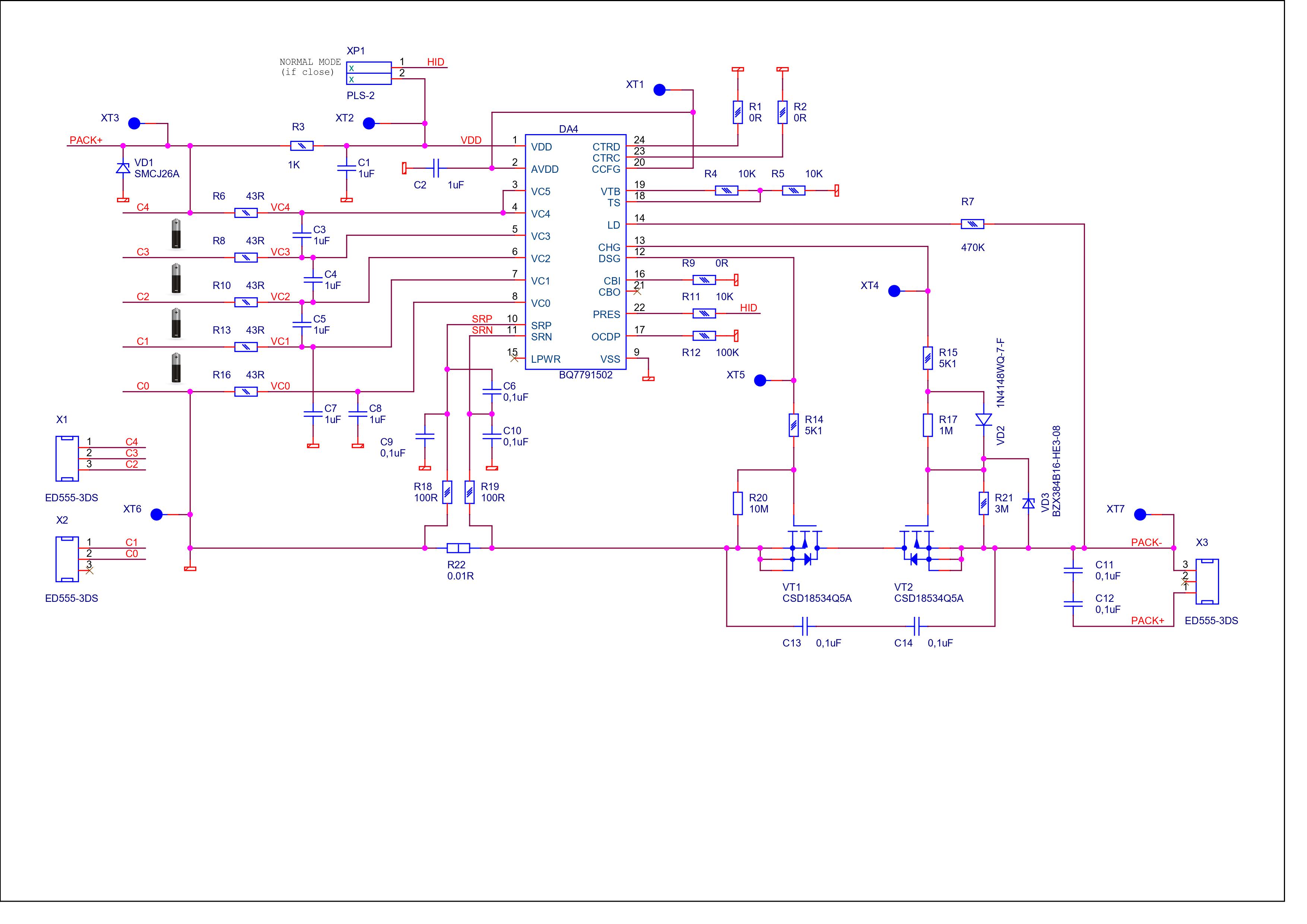
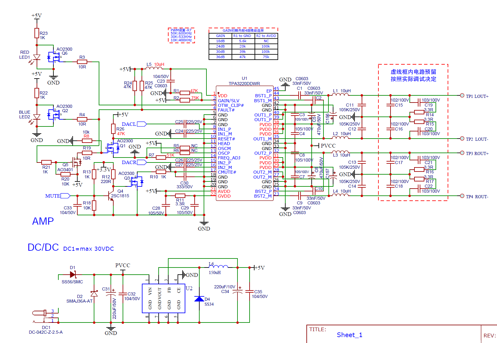
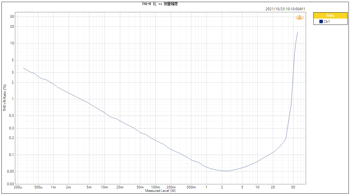
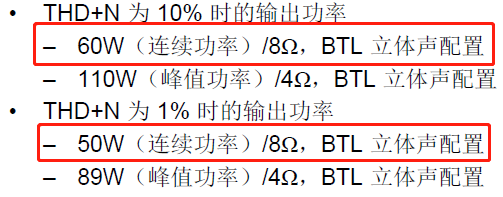
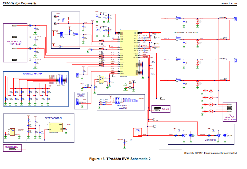
Question 1: according to the official data, when tpa3220ddwr is powered by 30V, when thd is 1%, 8 ohm power is 2 * 50W, and when thd is 10%, 8 ohm power is 2 * 60W. It is actually made according to demo parameters, which can not meet the official data. For the actual parameters, see my AP test diagram, attached figure 1. Schematic diagram, attached Fig. 2
Please help to see if there is any room for improvement and help to put forward improvement methods. Thank you
Question 2: according to the official data, the tpa3220ddwr provides 8 ohm thd = 10%, 2 * 60W continuous power, but in practice, it can only be 2 * 40W continuous power. When the sine wave is aged up to 1kHz, the protection time will become shorter and shorter with the increase of power. I consider that it may be related to the heat dissipation of my PCB,
However, if it is related to heat dissipation, please see question 3.
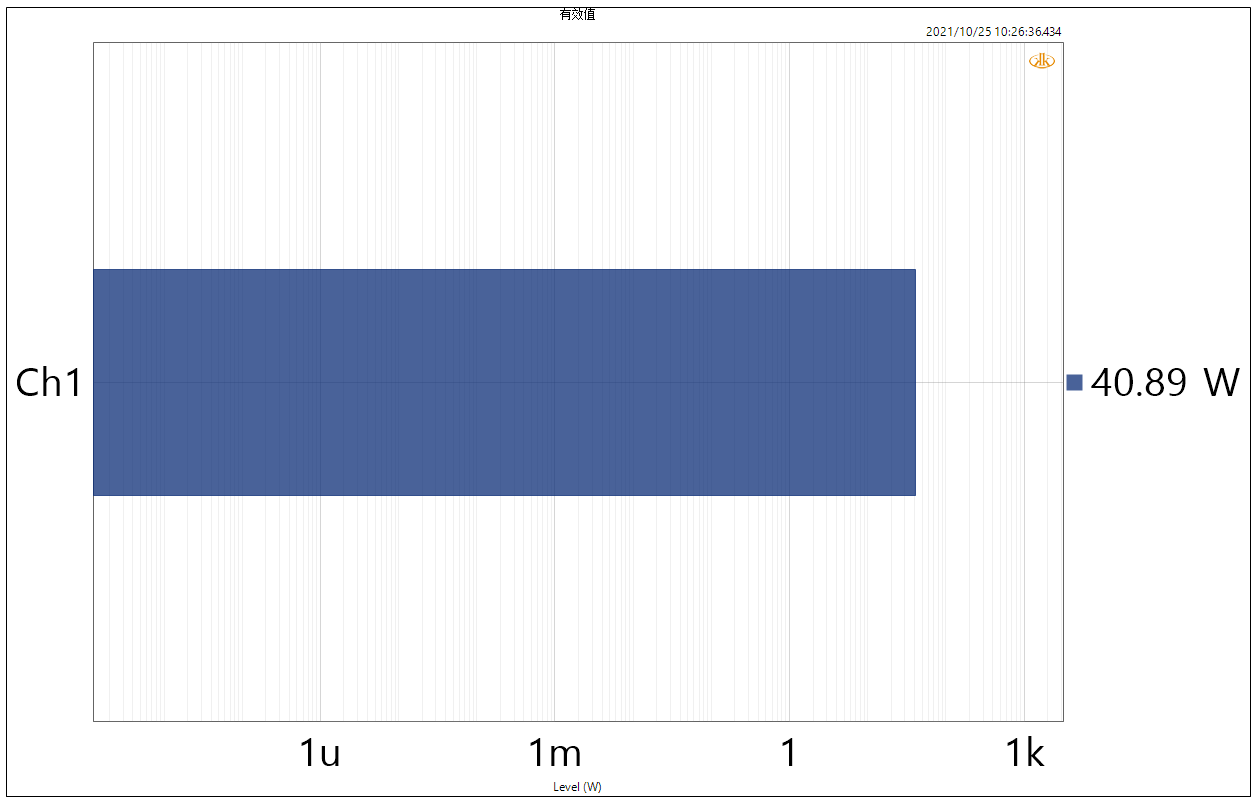
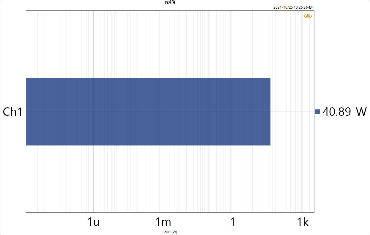
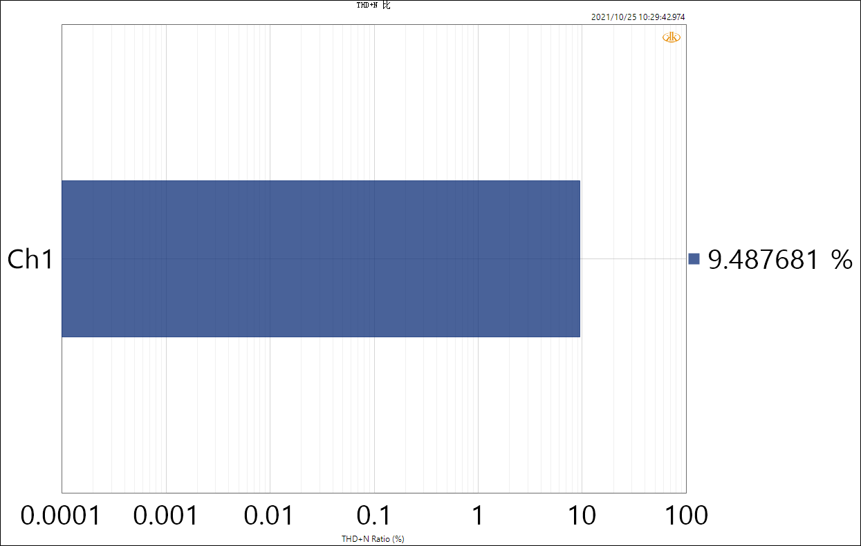
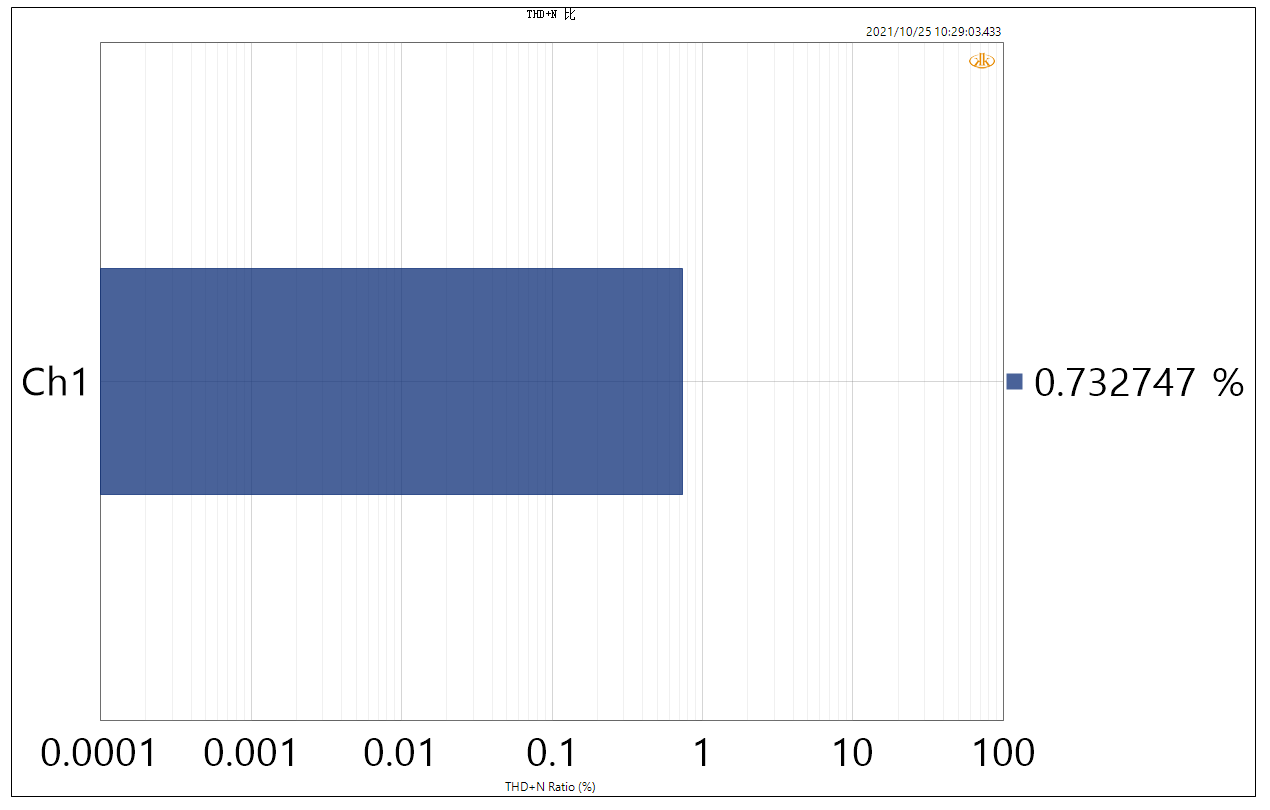
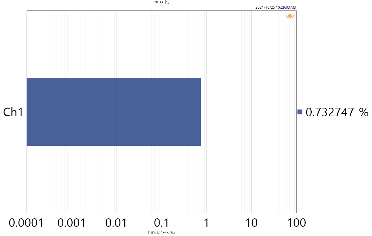
Question 3; Tpa3220ddwr, under the condition of 26V power supply, the output power is 41w, which can produce continuous power. See Annex 3 / 4 for specific power and distortion. Similarly, under the condition of 30V power supply, the output power is 43W, which can only last about 30s. See firmware 5 / 6 for specific power and distortion,
Under different voltages, similar power is output. 30V voltage is easy to protect, and 26V voltage can produce continuous power. Please help analyze the reason;
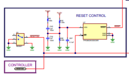
Question 4; Tpa3220ddwr, after protection, the fault pin outputs low level. After fault contact, it cannot be recovered automatically. It can be recovered only after the reset pin is reset, right? In the schematic diagram of Annex 1, check whether the circuit of R19 / R20 / R21 / R26 / Q1 / Q5 is feasible. After the fault protection action, Q5 turns on to make Q1 turn on, reset when reset is pulled low, and the fault turns to high level after reset. The actual test shows that the circuit cannot work normally, and the separate test is feasible. As long as it is closed-loop, it is not normal;
Excuse me, can automatic reset be realized after protection with tps3802k according to official data?
Early product has been using TPA3110/TPA3118, this TPA3220 is the first time to use, so TI trouble official technical support, give some help, thank you very much!