This thread has been locked.

If you have a related question, please click the "Ask a related question" button in the top right corner. The newly created question will be automatically linked to this question.

TAS2110: TDM clock error occurs when the output level is increase

Part Number: TAS2110

Hello,
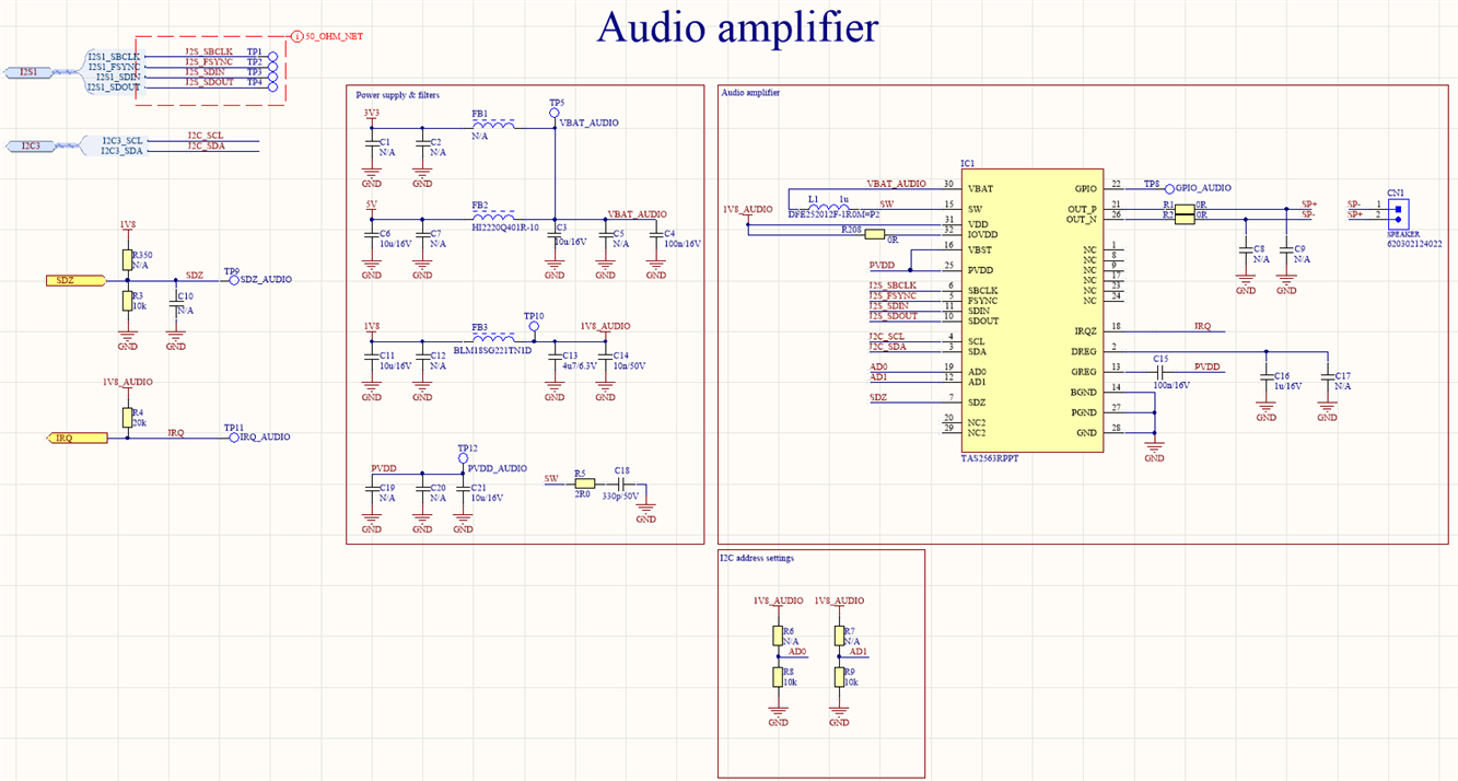
I work on a custom board with TAS2110. Below is the schematic (please don't see on MPN IC1 on the schematic):
/resized-image/__size/1333x768/__key/communityserver-discussions-components-files/6/TAS2110_5F00_schematic.png

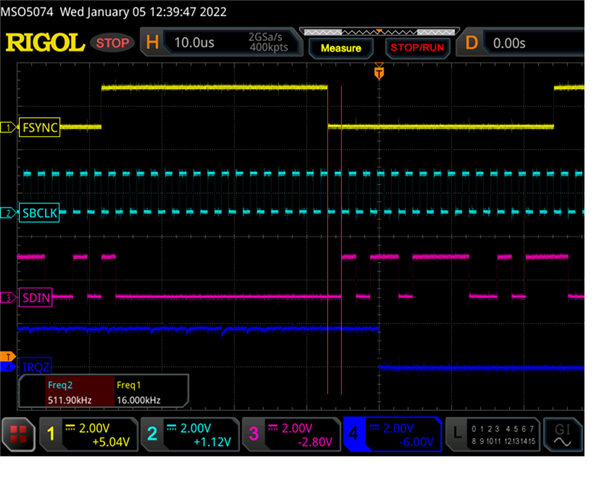
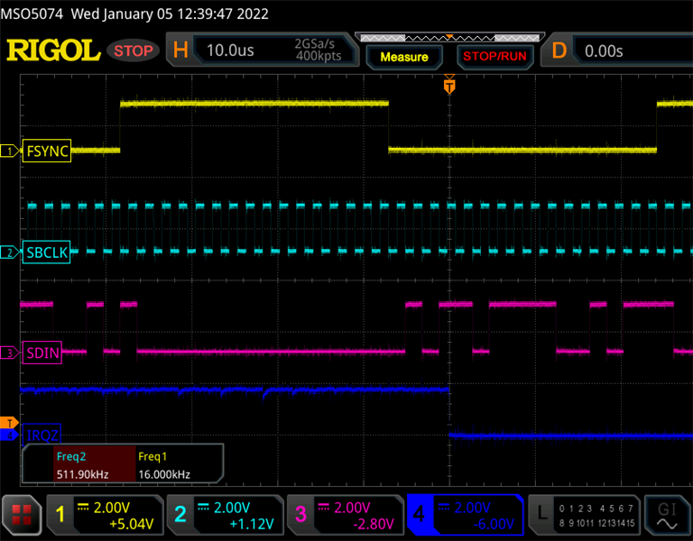
Speaker has 4ohm, Parameters of I2S:
FSYNC = 16k Hz
SBCLK = 512 kHz
channel - mono = left
signal source = sinewave 1kHz.
Resolution: 16bit
When I set register AMP_LEVEL below 0x06 amplifier works fine without errors, but when I set 0x06, 0x07 then interrupt occurs with error INT_LTCH0 = 0x04 (Interrupt due to TDM clock error).
My configuration TAS2110 sequence:
SDZ_LOW
DELAY 1s
SDZ_HIGH
DELAY 1s
REG_PAGE = 0x00
PWR_CTL = 0x02
MISC_CFG2 =0x20
PB_CFG1 = 0x0C
INT_MASK0 = 0x00
INT_MASK1 = 0x00
BOOST_CFG4 = 0x37
BOOST_CFG3 = 0xF4

REG_PAGE = 0x02
LIM_CFG5 = 0x30
LIM_CFG6 = 0x00
LIM_CFG7 = 0x00
LIM_CFG8 = 0x00

REG_PAGE = 0x00
PWR_CTL = 0x00

I check signal during interrupt but for my is ok.
/resized-image/__size/800x600/__key/communityserver-discussions-components-files/6/TAS2110_5F00_irq_5F00_sbclk0.png
Do you have any idea what I made wrong?

  • Hi Mateus.

    I'll double check the clock frequencies you're using are supported, although from a rough guess I think it should be.

    Have you tried to initially reduce the input source amplitude, set AMP_LEVEL to 0x06 as you mentioned, and then increase the amplitude from the source, instead of AMP_LEVEL?
    I'd like to check if this is related to the amplitude at the output or something else.

    Also wanted to ask what is your load impedance? Can you try with a higher impedance load?

    Best regards,
    -Ivan Salazar
    Applications Engineer

  • Hello,
    I did the test which you wanted. I change amp_level and MVC source amplitude. Below Is a simple table with results:

    AMP_LEVEL MVC source amplitude (0 - 16000) input current [mA] speaker impedance [ohm]
    0x14 11260 350 4
    0x10 11465 345 4
    0x06 11980 345 4
    0x02 12180 340 4
    0x08 12160 370 6

    My power supply was 5V with additional capacitors 4700uF + 470uF  and the test signal was 1kHz sine wave.
    When I set the above values of source amplitude then INI_LTCH0 was 0x04 or 0x06.
    Results look like the problem is in the input current limit. But I set BOOST_CFG4 to 4A input current limit.
    Do you have any ideas about what I made wrong?

  • Hi Mateus,

    I have completed some tests on my side, adding some comments below:

    • The default configuration from GUI is based on USB controller from EVM, in order to use this low rate and resolution please make sure to change the following:
      • Change Device Control view to Advanced mode
      • Scroll down to view TDM - Receiver settings
      • Set Word and Slot Length to 16bit
      • Set Receiver Offset to 0, this is important otherwise your input data would be "multiplied by 2" due to bit shifting
    • I can confirm the device is able to go up to 0dBFS input using 8-ohm load
    • EVM is triggering Overcurrent protection at around -2.5dBFS (5W output) using 4-ohm load, PCB design and passive components are main limiting factors

    Best regards,
    -Ivan Salazar
    Applications Engineer

  • Thank you for debugging on your side.
    I don't have the EVM board from TI. I use the custom board but I made it based on the schematic and layout from the TAS2110EVM User's Guide.
    I set: TDM_CFG2 = 0x10, but situation is the same. When I set additionally TDM_CFG1=0x00 then all time occurs interrupt INT_LTCH0 =0x04 or 0x06.
    I think that TDM_CFG1 must be set 0x01 because in my I2S signal is offset 1 clock before signal SDIN:
    Do you have any idea else?


  • Hi Mateus,

    Let me check on my side if the limitation I see for input higher than -2.5dBFS is the same as you're getting depending on the gain.
    Will get some further comments as soon as possible.

    Best regards,
    -Ivan Salazar
    Applications Engineer

  • Thank you. If it is possible, please use a 1kHz sine wave signal and measure the input current during using 5V VBAT.

  • Mateus,

    I ran the tests and got below results/comments:

    • I played 1kHz -0dBFS with different AMP_LEVEL settings starting from 10.5dBV (0x05), I can go up to 13dBV (0x0A) without triggering OCP
    • The above result is close to -2.5dBFS limitation from previous test, it can be down closer to -3dBFS which is equivalent to playing 0dBFS and reducing gain by 3dB
    • Perhaps in your system the higher current or ripple levels are messing up with the digital side then causing clock error before OCP?
    • 5V going to VBAT pin only is going up to ~2.8A and average ~1.25A.

    Best regards,
    -Ivan Salazar
    Applications Engineer

  • Thank you very much for this test.
    I reworked a little hardware - I used external cable for SBCLK (without connection on PCB) then I repeated test. Result was the same so my board have fault. I will buy eval board then I repeat test and redesign my custom board.
    I think that we can close this topic. Thank you one again.