Part Number: TAS5731M
Other Parts Discussed in Thread: PCM5102A, PCM9211, PCM2706,
I have a custom PCB with the same schematic of the EVM board.
I'm trying to initialize the chip, I have a workling i2c communication.
But I cannot get any sound from the amplifier.
On the same i2s bus I have a pcm5102a and it is playing the audio.
The source is the ADC in the a PCM9211; the same issue also
happends with a PCM2706 as a source (via the PCM9211).
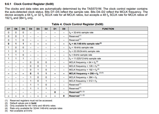
Sometimes register 0x02 have a 0x80 or 0xC0.
This is my current register dump,
PCM9211 is set with main output to DAC source,
main output goes to TAS5731M:
I: Reg 0x0000: 0b1101100(0x006C)
I: Reg 0x0001: 0b0(0x0000)
I: Reg 0x0002: 0b0(0x0000)
I: Reg 0x0003: 0b10100000(0x00A0)
I: Reg 0x0004: 0b11(0x0003)
I: Reg 0x0005: 0b0(0x0000)
I: Reg 0x0006: 0b0(0x0000)
I: Reg 0x0007: 0b1100000(0x0060)
I: Reg 0x0008: 0b110000(0x0030)
I: Reg 0x0009: 0b110000(0x0030)
I: Reg 0x000A: 0b110000(0x0030)
I: Reg 0x000E: 0b10010001(0x0091)
I: Reg 0x0010: 0b10(0x0002)
I: Reg 0x0011: 0b10101100(0x00AC)
I: Reg 0x0012: 0b1010100(0x0054)
I: Reg 0x0013: 0b10101100(0x00AC)
I: Reg 0x0014: 0b1010100(0x0054)
I: Reg 0x0019: 0b110000(0x0030)
I: Reg 0x001A: 0b1111(0x00F)
I: Reg 0x001B: 0b11000000(0x00C0)
I: Reg 0x001C: 0b10(0x0002)
I: Reg 0x0020: 0b0111101111110010(0x000017772)
I: Reg 0x0021: 0b00100001111(0x00000433)
I: Reg 0x0025: 0b110100111000101(0x000121345)
And those are the init values:
static Command TAS_INIT_TRIM = {0x1B, 0x00};
// Do this if using PCM2706 (16bit 24khz)
static Command TAS_INIT_FMT_16B = {0x04, 0x03};
static Command TAS_INIT_SVOL = {0x06, 0x00};
static Command TAS_INIT_CH3VOL = {0x0A, 0x30};
static Command TAS_INIT_CH2VOL = {0x09, 0x30};
static Command TAS_INIT_CH1VOL = {0x08, 0x30};
static Command TAS_INIT_CH2NDLY = {0x14, 0x54};
static Command TAS_INIT_CH1NDLY = {0x13, 0xAC};
static Command TAS_INIT_CH2DLY = {0x12, 0x54};
static Command TAS_INIT_CH1DLY = {0x11, 0xAC};
static Command TAS_INIT_CFGVOL = {0x0E, 0x91};
static Command TAS_INIT_CFGVOL = {0x20, 0x00, 0x01, 0x77, 0x72};
static Command TAS_INIT_MOD1 = {0x10, 0x02};
static Command TAS_INIT_RSVD1 = {0x0B, 0x00};
static Command TAS_INIT_MOD2 = {0x10, 0x02};
static Command TAS_INIT_BKND = {0x1C, 0x02};
static Command TAS_INIT_SHDWN = {0x19, 0x30};
static Command TAS_INIT_CFGVOL = {0x25, 0x01, 0x02, 0x13, 0x45};
static Command TAS_POST_MASTVOL1 = {0x07, 0xFF};
static Command TAS_POST_SYSCTG = {0x05, 0x00};
static Command TAS_POST_MASTVOL2 = {0x07, 0x60};
I have PVDD set at 12V, AVDD and DVDD are 3.3V.
On bootrap caps I have around 12V. Outputs A,B,C,D are at 6V
ON VREG: 3.1V
On VR_DIG I have: 1.8V
On GVDD_OUT: 7.0V
On SSTIMER: 3.1V
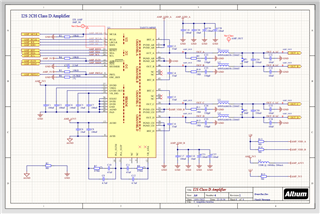
My messy schematic:
How I can throubleshoot this?