This thread has been locked.

If you have a related question, please click the "Ask a related question" button in the top right corner. The newly created question will be automatically linked to this question.

PGA2505: PGA2505 with limit voltage input of DSP

Part Number: PGA2505
Other Parts Discussed in Thread: OPA1637

Hello support team,

The problem here is from our customer.

They met some bottlenecks with PPGA2505 in products, and needs your comments:

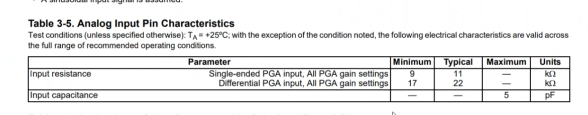
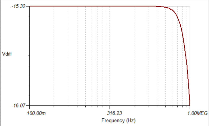
PGA2505 had max +-5V(VA+, VA- 5V power supply) output, and this output will go into the DSP, but DSP's input limited voltage is +-1V.

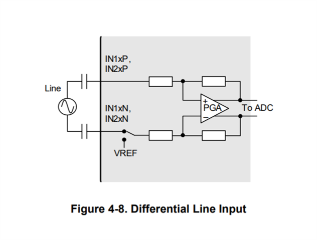
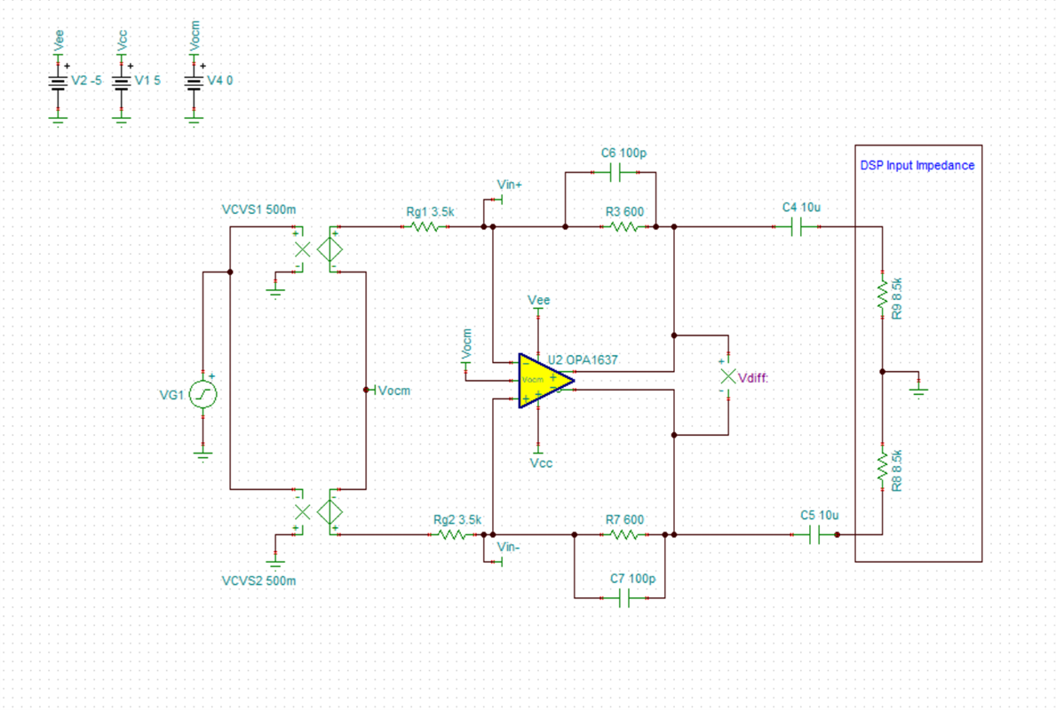
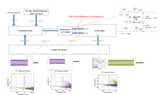
On the current design, they used a 15dB attenuator(Resistor divided) after PGA2505 to protect the DSP, and they found that the attenuator as figure below deteriorated the performance of DSP (THD+N) due to the series resistor between PGA2505&DSP(R214,R216).

The measurement setting of the attenuator is shown in below figure.

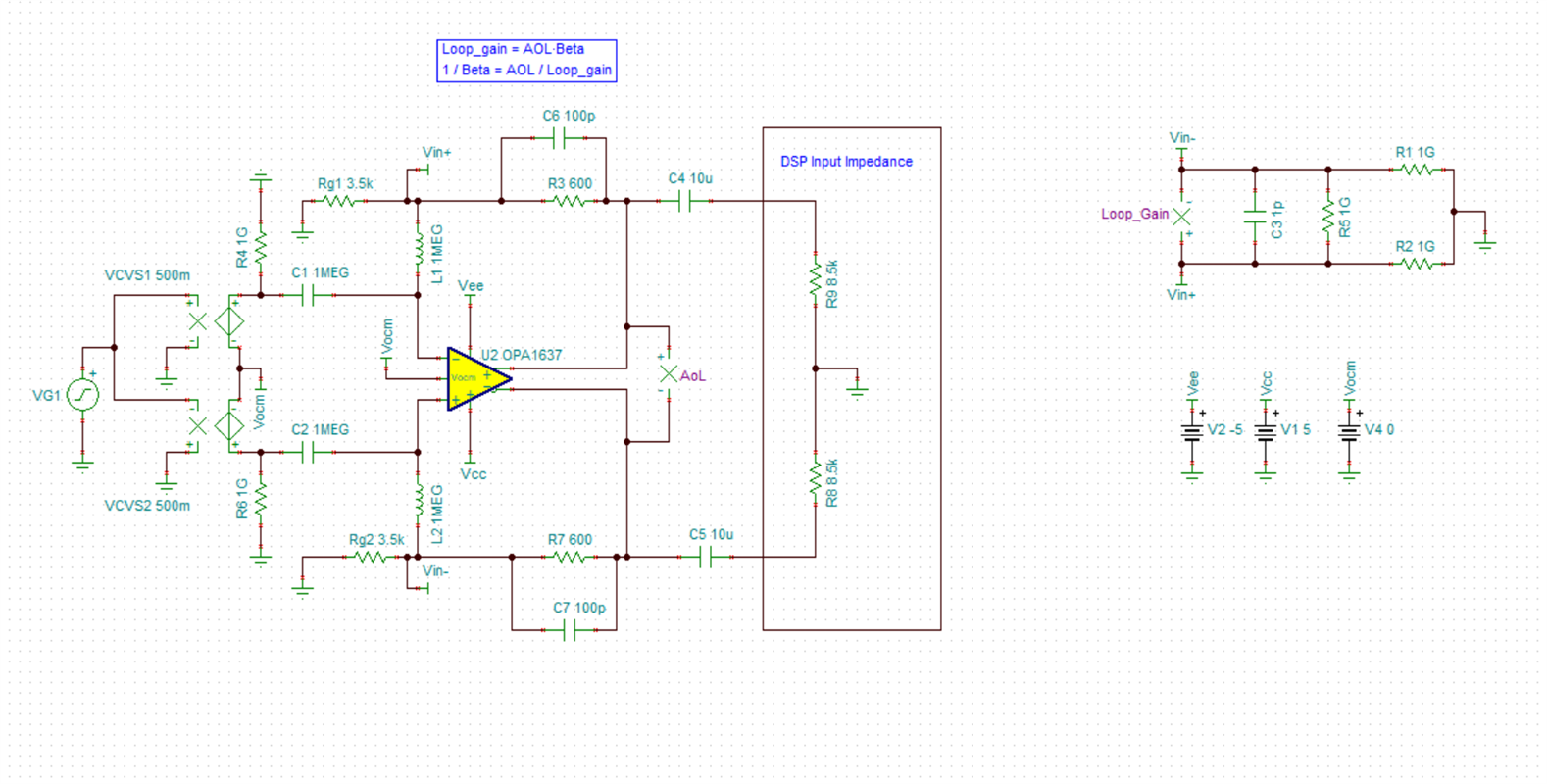
Would you have a +-1V Pre-amplifier to advise or any other comment for it?

DSP: Cirrus Logic CS47L90 

Best Regards,

Dave

  • The DSP input is really an ADC input, as the ADC is built into the DSP. 

    ADC inputs need to be driven by a low-impedance source, otherwise you get a degradation in noise and distortion.

    This is why every data sheet for every ADC shows them with the inputs driven by a buffer or op-amp.

    Look at the data sheets for any of TI's audio ADCs. You will see the ADC inputs driven by an op-amp or differential op-amp configured with gain less than unity (attenuating), as the typical use case is to take line-level audio which can swing to standard op-amp rails (±15V) to feed an input with a range of about 2 V centered around some offset (maybe 1.25 V or whatever).

  • Hello Dave,

    Looking at the product datasheet of the Cirrus Logic CS47L90 the input impedance characteristics are on page 12, and they show AC coupling to the input PGA on pages 32-33.

    A good and easier way to interface the PGA2505 is to use a fully differential amplifier as the attenuator into the DSP device. I have put together an example using the OPA1637 in Tina Ti. OPA1637 Attenuator.TSC

    Running an AC frequency sweep we can see our attenuation is roughly -15dB set by resistors R3, R7, Rg1 and Rg2. 

    We must check the stability analysis by including the input impedance parameters of the OPA1637 and the input impedance characteristics of the Cirrus Logic CS47L90 that will be connected to the output of the OPA1637. I have put together a Tina Ti simulation to show the stability analysis with these parameters included. 

    Circuit for checking stability of Fully Differential Amplifier with characteristic input impedances included:

    Below we have 98 degrees of phase margin. This circuit is very stable. From here larger AC coupling capacitors could be chosen depending on how low in frequency the customer would like to go. After modifying the capacitors stability would have to be examined again with the new values. 

    OPA1637 Attenuator Stability.TSC

    For more information on stability analysis for fully differential amplifiers, we have a video training course here:

    https://training.ti.com/ti-precision-labs-op-amps-fully-differential-amplifiers-fda-stability-and-simulating-phase

    I would recommend a method such as this to avoid the THD+N increase seen with the passive component attenuator method. 

    Best Regards,

    Chris Featherstone