This thread has been locked.

If you have a related question, please click the "Ask a related question" button in the top right corner. The newly created question will be automatically linked to this question.

TPA3144D2: Constant 4.6 kHz tone on the speakers

Part Number: TPA3144D2
Other Parts Discussed in Thread: PCM2900C, PCM2900

Hi everyone!

I designed a board that among other things uses a TPA3144D2 to drive a pair of 8Ω / 2-watt speakers. The source for the audio is a PCM2900C audio codec.

It's configured in the following way:

GAIN: 20dB / LIMRATE: fast / LIMTHRES: 1.46V / SSCTRL: SS2 Modulation / 1SPW: BD-modulation

It basically works as intended, but I ran into one problem.

As soon as the TPA3144D2 is enabled there is a rather clean tone around 4.6kHz on the speakers. The noise disappears if I short the inputs to ground.

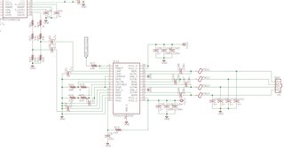
This is the relevant part of the schematic:

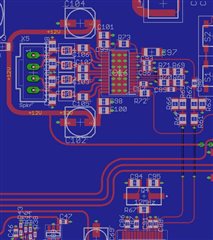
And this is the corresponding part of the layout:

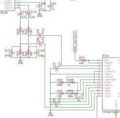
Trying to solve the problem I first changed the input network to the following configuration. This didn't solve the problem.:

I then started to remove power from other parts of the board until the lone TPA3144D2 was left, powered by a battery, the 4.6 kHz tone still emanating from the speakers.

Any suggestions would be appreciated.

Best Regards, Raoul

  • Hi Raol,

    Did you power off PCM2900 to check the noise?

    And did you use external power to power up AMP? 

    According to your description, the noise seems be from audio input. I am not sure it is from PCM2900 or other layout coupling. Usually RC filter should be added between codec and AMP.


    Regards,

    Derek

  • Hi Derek

    Thank you very much for your assistance!

    Yes, the PCM2900 was powered off to check the noise.

    In fact, I isolated the power to the AMP and powered the whole board off while running the AMP with external power. I even suspected my lab power supply, so I used a battery and resistor divider to power the AMP with 12 volts and enable it with 5 volts on the SD pin.

    I tried to implement an RC filter with the components I had at hand when I changed the input network, but it's certainly not ideal.

    Do you have a suggestion how to best interface the codec and the AMP? If my calculations are correct, I need an attenuation of about 4.7 dB between the codec and AMP for 2 watts maximum output power into an 8 Ω speaker.

    Best Regards, Raoul

  • Hi Raol,

    I am sorry I am not familiar with PCM2900 device. But the RC filter usually is must between codec and AMP, but the RC value should be check with PCM2900 device support.

    I saw the distance between AMP and codec is not very far. But the audio traces have two vias, so the trace layout go through several layers? It is risk. 

    You can do hardware rework, disconnect the PCB trace, and using wire to connect codec and AMP input directly.

    Regards,

    Derek

  • Hi Derek

    Ok, I think I'll redesign the PCB to introduce a proper RC filter, eliminate any vias in the audio traces, ground LINN and RINN near the codec, and maybe enlarge the ground plane in the top layer around the AMP.

    But otherwise, you don't see an obvious problem in the circuit or layout around the TPA3144D2?

    Best Regards, Raoul

  • Hi Raoul,

    I did not see other obvious problem on SCH and PCB.

    By the way, the input DC caps are 4.7uF. The typical caps value is 1uF. Too large cap value may bring pop noise when power up.

    Regards,

    Derek