


At present, TPA311D1 is used to design the following circuit diagram, but no matter how the input waveform changes, the output will not change, can you help to check which side is designed, is there any problem?
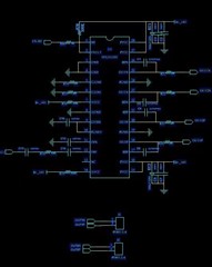
Schematic diagram
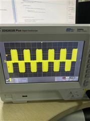
The output
At present, TPA311D1 is used to design the following circuit diagram, but no matter how the input waveform changes, the output will not change, can you help to check which side is designed, is there any problem?
Schematic diagram
The output
