This thread has been locked.

If you have a related question, please click the "Ask a related question" button in the top right corner. The newly created question will be automatically linked to this question.

TLV320AIC3212: Suggestions for reducing background noise?

Part Number: TLV320AIC3212
Other Parts Discussed in Thread: AM5728
Hello TI Team ,
We are using Audiocodec TLV320AIC3212 with TI AM5728 SOC on a custom board. After integrating the device with the system, we are in the process of tweaking the Audiocodec parameters for best performance as the board is to be used for VIOP applications.
1. We require to optimise the inbound stream at ADC for lesser background noise. Please find attached wav files for recording the input stream at 16Khz. ,
Please suggest how we can reduce the background sound / noise.
 
2. Can tweaking AGC paramters be helpful ? Currently AGC is disabled in our recording.
 
3. Can adaptive Filters be used for the same ?? If yes please share details.
4. The register settings for the MIC input are as follows : ( In our board the Analog input interfaces are set to MONO )
======================================================
#!/bin/sh                                                                                                                                                                                                                                                                                                                                                                       
#op channel                                                                                                                                                                                                                                                                                                                                                                     
/usr/sbin/i2cset -f -y 3 0x18 0x00 0x00
#Set to Page-0                                                                                                                                                                                                                                                                                                                          
/usr/sbin/i2cset -f -y 3 0x18 0x3f 0xc0
#Left and Right DAC channel is powered UP                                                                                                                                                                                                                                                                                               
/usr/sbin/i2cset -f -y 3 0x18 0x40 0x00
#Left and Right DAC un-muted                                                                                                                                                                                                                                                                                                            
/usr/sbin/i2cset -f -y 3 0x18 0x00 0x01
#Set to Page-1                                                                                                                                                                                                                                                                                                                          
/usr/sbin/i2cset -f -y 3 0x18 0x03 0x00
#Left DAC in mode PTM_P3, PTM_P4                                                                                                                                                                                                                                                                                                        
/usr/sbin/i2cset -f -y 3 0x18 0x04 0x00
#Right DAC in mode PTM_P3, PTM_P4                                                                                                                                                                                                                                                                                                       
                                                                                                                                                                                                                                                                                                                                                                                
#HANDSET- OFF                                                                                                                                                                                                                                                                                                                                                                    
/usr/sbin/i2cset -f -y 3 0x18 0x08 0x00
#Output commom mode for HP & REC drivers is set to Input Common Mode                                                                                                                                                                                                                                                                    
/usr/sbin/i2cset -f -y 3 0x18 0x24 0x7f
#LOL Output Not Routed to RECP Driver (Default)                                                                                                                                                                                                                                                                                         
/usr/sbin/i2cset -f -y 3 0x18 0x25 0x7f
#LOR Output Not Routed to RECM Driver (Default)                                                                                                                                                                                                                                                                                         
/usr/sbin/i2cset -f -y 3 0x18 0x26 0x7f
#IN1L Input Not Routed to RECP Driver (Default)                                                                                                                                                                                                                                                                                         
/usr/sbin/i2cset -f -y 3 0x18 0x28 0x39
#Power-Down RECM & RECP and RECP Volume Control is Muted                                                                                                                                                                                                                                                                                
/usr/sbin/i2cset -f -y 3 0x18 0x29 0xb9
#RECM Volume Control is Muted                                                                                                                                                                                                                                                                                                           
/usr/sbin/i2cset -f -y 3 0x18 0x2a 0x08
#Force Caliberate Offset                                                                                                                                                                                                                                                                                                                
                                                                                                                                                                                                                                                                                                                                                                                
#HEADSET- OFF                                                                                                                                                                                                                                                                                                                                                                    
/usr/sbin/i2cset -f -y 3 0x18 0x1f 0xb9                                                                                                                                                                                                                                                                                                                                         
/usr/sbin/i2cset -f -y 3 0x18 0x20 0xb9                                                                                                                                                                                                                                                                                                                                         
/usr/sbin/i2cset -f -y 3 0x18 0x1b 0x33
#Left DAC -> HPL | Right DAC -> HPR | HPL & HPR Powered Down                                                                                                                                                                                                                                                                            
                                                                                                                                                                                                                                                                                                                                                                                
#SPEAKER-ON                                                                                                                                                                                                                                                                                                                                                                     
/usr/sbin/i2cset -f -y 3 0x18 0x16 0xc3 #LOL & LOR output driver power UP                                                                                                                                                                                                                                                                                                       
/usr/sbin/i2cset -f -y 3 0x18 0x2d 0x06 #SPKL Power-UP, SPRK Power down                                                                                                                                                                                                                                                                                                         
/usr/sbin/i2cset -f -y 3 0x18 0x2e 0x00 #Route LOL to SPK-Left @ 0dB                                                                                                                                                                                                                                                                                                            
/usr/sbin/i2cset -f -y 3 0x18 0x2f 0xff #Route LOR to SPK-Right @ 0dB                                                                                                                                                                                                                                                                                                           
/usr/sbin/i2cset -f -y 3 0x18 0x30 0x10 #Set Speaker Gain for SPKL@6DB and SPKR @ MUTE                                                                                                                                                                                                                                                                                          
                                                                                                                                                                                                                                                                                                                                                                                
#adc config                                                                                                                                                                                                                                                                                                                                                                     
/usr/sbin/i2cset -f -y 3 0x18 0x00 0x01 #Setting to Page-1                                                                                                                                                                                                                                                                                                                      
/usr/sbin/i2cset -f -y 3 0x18 0x08 0x00 #Output commom mode for HP & REC drivers is set to Input Common Mode                                                                                                                                                                                                                                                                    
/usr/sbin/i2cset -f -y 3 0x18 0x33 0x15 #MicBias control power UP                                                                                                                                                                                                                                                                                                               
/usr/sbin/i2cset -f -y 3 0x18 0x34 0x04 #IN3L selected to Left MIC PGA, IN1R not selected                                                                                                                                                                                                                                                                                       
/usr/sbin/i2cset -f -y 3 0x18 0x36 0x40 #CM1 selected (RIN-20K), CM2 not selected                                                                                                                                                                                                                                                                                               
/usr/sbin/i2cset -f -y 3 0x18 0x37 0x00 #IN1R, 2R, 3R not selected                                                                                                                                                                                                                                                                                                              
/usr/sbin/i2cset -f -y 3 0x18 0x39 0x00 #CM not selected                                                                                                                                                                                                                                                                                                                        
                                                                                                                                                                                                                                                                                                                                                                                
/usr/sbin/i2cset -f -y 3 0x18 0x3b 0x3c #Left MICPGA Gain is enabled with 30dB                                                                                                                                                                                                                                                                                                  
/usr/sbin/i2cset -f -y 3 0x18 0x3c 0x80 #Right MICPGA Gain is enabled at                                                                                                                                                                                                                                                                                                        
/usr/sbin/i2cset -f -y 3 0x18 0x3d 0x00 #Left & Right ADC Modulator gets input from Left & Right ADCPGA                                                                                                                                                                                                                                                                         
/usr/sbin/i2cset -f -y 3 0x18 0x00 0x00 #Setting to Page-0                                                                                                                                                                                                                                                                                                                      
/usr/sbin/i2cset -f -y 3 0x18 0x51 0x80 #Left & Right Channel ADC power up                                                                                                                                                                                                                                                                                                      
/usr/sbin/i2cset -f -y 3 0x18 0x52 0x00 #Left & Right ADC channel un-mute with 0dB                                                                                                                                                                                                                                                                                              
                                                                                                                                                                                                                                                                                                                                                                                

KINDLY SUGGEST WAY FORWARD
  • Hi,

    Attached is what I have extracted from your registers above. I don't see your clock configuration like what MCLK are you providing, the format, PLL enable/disable etc.

    Noise could also come from wrong clock configuration, the board itself or the recording environment.

    config.xlsx

    I suggest you debug the path separately, just ADC path and record with Audacity/GoldWave. 

    Check with pure tone from a known source to validate your clock/ADC settings. If this is good then you can debug the MIC input side.

    Here are some common noise in audio codec you can check.

    https://www.ti.com/lit/an/slaa749/slaa749.pdf?ts=1659122117928&ref_url=https%253A%252F%252Fwww.ti.com%252Fproduct%252FTLV320AIC3212

    Regards.

  • Hi ,

    Our MCLK is 22.5792 MHz ( Same as in AM5728 EVM ) and the format is dsp_b.  We are not using audiocodec PLL.

    In our setup, SOC is MASTER, Audiocodec is in SLAVE mode. We are running WCLK at 11KHz.

    We have gone through this document SLAA749 how to isolate the type of noise introduced in the ADC path.

    - Can AGC help in attenuating the Noise ?? If yes, What values of its parameters can be used to reduce the background noise ?

    Kindly suggest.

  • Your MCLK is not a multiple integer of the sampling, so you will need to use PLL.

    See section 2.7 of this reference guide till section 2.7.1 for configuring the clock. Make sure the clock is not exceeding the maximum allowable frequency like in table 2-40 and 2-41.

    https://www.ti.com/lit/ug/slau360/slau360.pdf?ts=1659365738185&ref_url=https%253A%252F%252Fwww.ti.com%252Fproduct%252FTLV320AIC3212

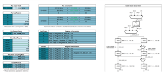
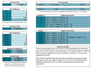
    For example you can use the following divider in the clock configuration to get 11KHz sampling by first reducing the MCLK by half from 22.5792MHz to 11.2896MHz by configuring PLL_CLKIN_DIV to 2 then configure the rest of the divider to get the sampling rate you need.

    I have provided an example as shown below.

    You can download this PLL clock sheet from this product folder and use one that has similar clock tree configuration like AIC325x.

    https://www.ti.com/product/TLV320AIC3254-Q1

    This is clock configuration issue and AGC will not remove the noise.

    Regards.

  • Hi Peter ,

    1. As per our understanding, Since SoC(master) is driving the sync clocks to codec(slave), then codec PLL won't
    affect the BCLK, WCLK. 

    2. Our MCLK, which is 22579200 Hz, is integer multiple of 44100 Hz, 22050 Hz and 11025 Hz.

    3. We also verified the same with hardware probing, WCLK, BCLK are being generated with correct values wrt any of the above sampling rate.

    I am attaching a sample recorded at 11025 Hz. Considering the above statements, why do I hear noise in the attached sample??!


    Kindly guide.

  • Hi,

    1. The ADC/DAC block requires clock so it needs to be configured respectively following the clock tree structure shown in the reference guide and it has the min and max frequency requirement see table 2-41. 22.5792MHz is below the min if PLL is not used.
    2. I thought initially it's exactly 11KHz of sampling rate, so here is the PLL configuration for 11.025KHz.

    Please configure the clock as recommended above to ensure there's not an issue with the clock settings.

    Regards.

  • Hi Peter ,

    We tried enabling the PLL and using the suggested values for the P,J,R,D and other clock coefficients.

    There was not much improvements in noise, also the overall sound became feeble. Again I would like to re-iterate, "if our CODEC is in SLAVE mode then clocks (MCLK, BCLK,WCLK) are coming from SOC , should we enable the PLL at CODEC ?"

    The following commands were run to do the suggested PLL enabling experiment.

    #Commands to set various values with suggested PLL related register values
    
    /usr/sbin/i2cset -f -y 3 0x18 0x00 0x00
    /usr/sbin/i2cset -f -y 3 0x18 0x06 0x92 #P and R
    /usr/sbin/i2cset -f -y 3 0x18 0x07 0x04 #J
    /usr/sbin/i2cset -f -y 3 0x18 0x08 0x13 #D MSB
    /usr/sbin/i2cset -f -y 3 0x18 0x09 0x88 #D LSB
    /usr/sbin/i2cset -f -y 3 0x18 0x0B 0x88 #NDAC
    /usr/sbin/i2cset -f -y 3 0x18 0x0C 0x83 #MDAC
    /usr/sbin/i2cset -f -y 3 0x18 0x0D 0x01 #DOSR MSB
    /usr/sbin/i2cset -f -y 3 0x18 0x0E 0x80 #DOSR LSB
    /usr/sbin/i2cset -f -y 3 0x18 0x12 0x88 #NADC
    /usr/sbin/i2cset -f -y 3 0x18 0x13 0x89 #MADC
    /usr/sbin/i2cset -f -y 3 0x18 0x14 0x80 #AOSR

    2. Is there some document or some strategy to select the clocking and divisors ? The Application Reference Guide mentions all the options How should we select which one is applicable to our design ?

  • Your setting is not correct with PLL enable, see attached sheet for comments.

    1588.config.xlsx

    As mentioned above, the modulator needs its clock like ADC_MOD_CLK or DAC_MOD_CLK etc., though the codec is slave you still need to configure the source of the modulator clock as shown in the clock generation section in reference guide.

    If you don't want to enable PLL, you can do that too just make sure you provide the correct NDAC/MDAC/DOSR that will give the correct 11.025K sampling.

    The reference guide is your source, you can read the DAC setup (2.5.6) or ADC setup section 2.4.3.6 to start. Obviously you need to make sure the clock limitations are not violated which also mentioned in the reference guide.

    Use the PLL calculator link provided above to help with the divider ratio.

    Regards.

  • Hello,

    As suggested by you, DAC and ADC setup sections were referred from the Application Reference Guide.

    • PLL is Power DOWN.

    • DAC_CLCKIN and ADC_CLCKIN is getting sourced through MCLK1 which is kept equal to 2257900.

    Please verify the following Setup:

    DAC Setup (Section 2.5.6)

    1. MDAC – 4

    2. NDAC – 2

    3. DOSR – 256

    4. DAC_CLKIN = MCLK1 (Set by Register B0_P0_R4 : 0x00)

    which is satisfying the following conditions

    a) DAC_FS = DAC_CLCKIN / (DOSR * NDAC * MDAC)

    DAC_FS = 22579200 / ( 4*2*256)

    DAC_FS = 11025 (which is equal to our sampling rate value)

    b) 2.8MHz < DOSR * DAC_FS < 6.2Mhz

    28,00,000 < 256 * 11025 < 62,00,000

    28,00,000 < 28,22,400< 62,00,000

    c) (MDAC* DOSR) / 32 >= RC

    (4*256) / 32 >=RC

    32>=RC

    ADC Setup (Section 2.4.3.6)

    1. MADC – 4

    2. NADC – 2

    3. AOSR – 256

    4. ADC_CLKIN = MCLK1 (Set by Register B0_P0_R4 : 0x00)

    which is satisfying the following conditions

    a) ADC_FS = ADC_CLCKIN / (AOSR * NADC * MADC)

    ADC_FS = 22579200 / ( 4*2*256)

    ADC_FS = 11025 (which is equal to our sampling rate value)

    b) 2.8MHz < AOSR * ADC_FS < 6.2Mhz

    28,00,000 < 256 * 11025 < 62,00,000

    28,00,000 < 28,22,400 < 62,00,000

    c) (MADC * AOSR) / 32 >= RC

    (4*256) / 32 >=RC

    32>=RC

    Observations:

    1. We are verifying the noise by using linux commands – arecord and aplay. There is no apparent difference in the noise on setting different divisor values.

    Queries :

    1. Is there any way to verify the value of ADC_FS and DAC_FS – either by printing the same in driver code or through Hardware probing?

    2. How to set the processing block and filter type?

    3. I could see some Powertune registers in ADC setup. Can powertune and performance register needs to be configured to eliminate noises?

  • The above settings look correct for the DAC_CLKIN/ADC_CLKIN and you have verified it has the correct WCLK, BCLK and the audio format so I believe the codec setting is correct and noise is likely from your system/board. You can check with a pure sine tone on IN3L from a known source and record.

    I'm not a Linux expert so I can't comment on Linux implementation/configuration.

    • For ADC_FS/DAC_FS, you can refer to reference guide to route this signal out as shown in Figure 2-46.
    • There's register (B0_P0_R60/R61) which sets the different PRB. This PRB has its associated filter.
    • Powertune is to balance power and performance and not to eliminate noise. 

    Regards.