This thread has been locked.

If you have a related question, please click the "Ask a related question" button in the top right corner. The newly created question will be automatically linked to this question.

TAS5414CQ1PHDEVM: Latest version of the schematic

Part Number: TAS5414CQ1PHDEVM
Other Parts Discussed in Thread: TAS5414C,

Hi,

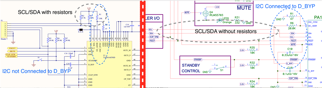
I am trying to build the TAS5414C evaluation board, which I would also like to use as a normal amplifier. I found multiple schematics and documents related to this.

Option-1. TAS5414CQ1PHDEVM Eval board, under Hardware development
Option-2. ASSEMBLY DRAWING, under Design & Tools simulation.

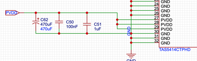
Tho. much of a design in mostly identical, but there are still few differences e.g at power side, 4 33uF capacitors are used in Option-1 while only 2 are used in Option-2.

For PVDD, 2 1uF/50V capacitors are used in Option-1 while 0.1uF/50V capacitor is used in Option-2.

My question is, which sciatic should I follow? Option-2, as date-wise its recent one.

My other question is, what design changes are required to get 79W/Ch? As Option-1 states that the input is 12V.

As per data sheet options,

– 28 W/Ch Into 4 Ω at 14.4 V
– 50 W/Ch Into 2 Ω at 14.4 V
– 79 W/Ch Into 4 Ω at 24 V

I may need to provide 24V input. Is that sufficient or are there any additional changes required to the schema?

Regards
-Mayuresh

  • Hi Mayuresh

      For your question. We'd recommend to put 1uF+0.1uF MLCC cap close to the PVDD pin of our device, this is mostly for EMC purpose, could reduce the switching ringing. Besides MLCC cap, a large capacitor is also needed, to keep the PVDD voltage stable, better for THD. Usually use some electrolytic capacitor would be fine, not that expensive also could easily reach high capacitance to hundreds μF.

       For your second question, the 24V voltage would be the most important, doesn't need other change.

  • Hi Shadow .. thanks for the reply. I am still little confused as to which schematic should I follow? While I was working on the new schema, I found following changes and need some help/clarifications,

    1. All 8 resistors before 10nF/00.1uF capacitors near Analog output capacitors are removed. Should I follow earlier design and keep them or follow new design and remove them?

    2. In old design, SDA/SCL are directly connected to the device VS in new schematic 4.7K resistor are used with 3.3V before connecting to the device. Are these resistors required or should I remove them?

    3. I2C is connected to D_BYP. As I was reading the data sheet, this means that the device will be in slave 3 mode. I am also working on a DSP (ADAU1701) and will be using it's DAC out (4 channels) to connect to this AMP. This in situation, my guess is that the AMP should be in master mode and not slave. So I should avoid connecting I2C to D_BYP Am I correct?

    Other option is to have a switch between I2C and D_BYP to switch between master/slave mode?

    Any help would be appreciated.

    Thanks
    -Mayuresh

  • Adding image for better explanation 

  • Hi Mayuresh

    All 8 resistors before 10nF/00.1uF capacitors near Analog output capacitors are removed. Should I follow earlier design and keep them or follow new design and remove them?

     Seems I didn't find this document, not seeing these resistors. But at input port, they should be used for filter purpose. It's not very essential component, you could decide for your system.

    n old design, SDA/SCL are directly connected to the device VS in new schematic 4.7K resistor are used with 3.3V before connecting to the device. Are these resistors required or should I remove them?

    The pull up resistor is essential for I2C communication system, there should be at least one place in your system to give pull up for both SCL and SDA. Not have to be close to our device.

    I2C is connected to D_BYP. As I was reading the data sheet, this means that the device will be in slave 3 mode. I am also working on a DSP (ADAU1701) and will be using it's DAC out (4 channels) to connect to this AMP. This in situation, my guess is that the AMP should be in master mode and not slave. So I should avoid connecting I2C to D_BYP Am I correct?

    Yes, use Master mode would be fine, no need to use slave mode.

  • Hi Shadow .. so basically use 3 caps 1uF MLCC + 0.1UfMLCC + 100uF electrolytic capacitor all in parallel ? See image.

    Thanks.

  • Hi Mayuresh

       Yes, this is recommended by us.