This thread has been locked.

If you have a related question, please click the "Ask a related question" button in the top right corner. The newly created question will be automatically linked to this question.

PCM6340-Q1: MIC input circuit and diagnose problems

Part Number: PCM6340-Q1

When we used  PCM6340QRTVRQ1, we faced the below problem in our project.

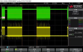
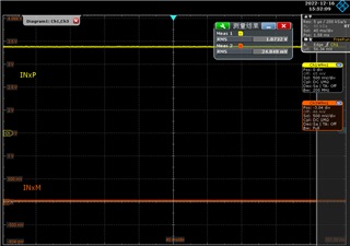
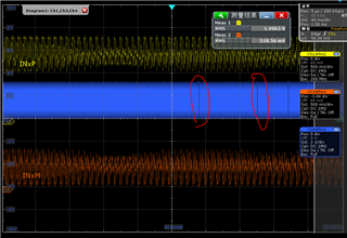
The BCLK (3.072Mhz) is intermittent, If you talk to Microphone(Input to ADC), BCLK will output 3.072MHz, when there is no sound ,BCLK is 3.3V(high level).

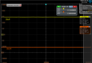
We check the registers of the chip, found there are some fault report like: INxM short to ground detected. 

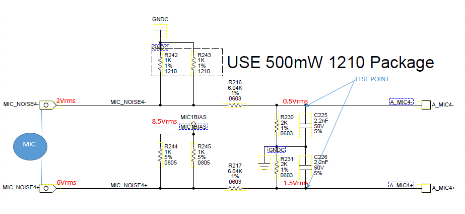
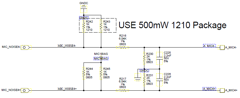
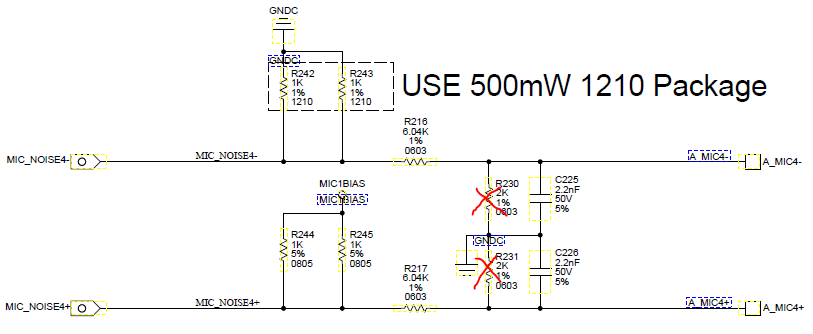
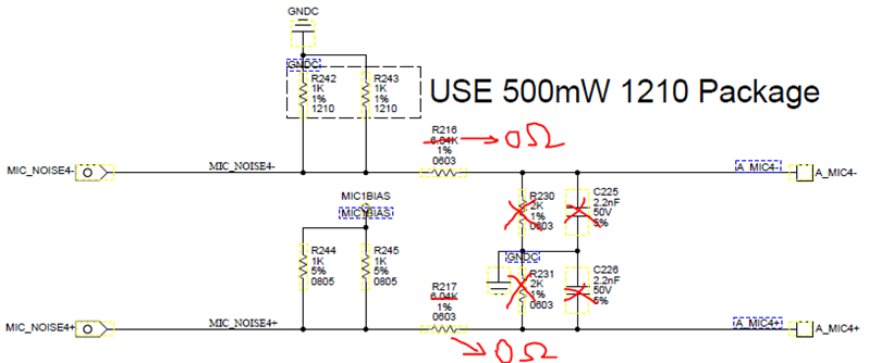
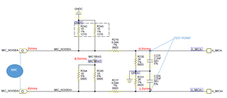
Our input circuit as below:

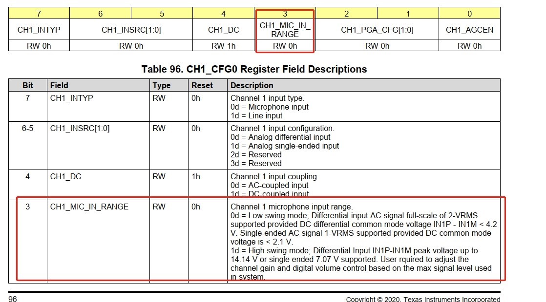
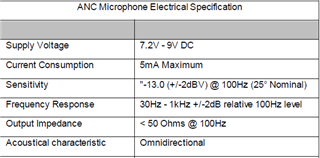
I want to make sure that can we connect R232 R231 to Ground? We set the Differential input full-scale AC signal voltageis 2Vrms.In order to prevent the MIC output from being greater than 2V, the resistance partial voltage is used.

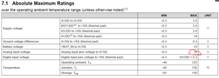
But we found the IC have DIAG_CFG1 Register ,there are a lot of threshold values as below:

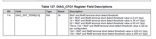
Does the circuit we used need to adjust the chip's DIAG_CFG1 Register threshold Settings to avoid faults?

If we use the default DIAG_CFG1 Register threshold,  the faults occur,Can we set PD_ON_FLT_CFG[1:0] to 0(Faults event are not used for ADC and MICBIAS power down),so the BCLK do not stop output.

Because we use Diagnostic SAR monitor data to set DIAG threshold (short to Batt 、short to GND......)and do not use the CHx_LIVE Register to Judge short circuit state,can we do not deal with the chip's DIAG register fault?

  • We try to set up PD_ON_FLT_CFG[1:0] to 0, found the Diagnostic SAR monitor data to set DIAG threshold is changed,why PD_ON_FLT_CFG affects SAR monitor data? Could you please explain the specific reason?


Need your support

Thanks.

  • Shall respond Thursday

  • Is there any update?

  • What kind of mic do you have?. Please disconnect the pulldowns, disable the diagnostics with I2C.

    Also please send me the Oscilloscope plot of DC Voltages on inverting and non inverting pin of ADC.

  • 1.ANC MIC

    Spec as below:

    2.ADC will work nomal while disable the diagnostics with I2C(adjust 0X64 ) , but we need diagnostic function, need READ SAR monitor data,if we disable diagnostics with I2C,SAR can not work.

    3.This is the Oscilloscope plot of DC Voltages on inverting and non inverting pin of ADC. 

    With MIC connect:

    Without MIC:

    Thanks.

  • Sometimes when we input Large sounds into the Microphone with Low frequency Content, the DC Level of the Pins drops to a Level low enouigh to trigger a fault threshold . You should place the INXP on an Oscilloscope with Mic Connected  an audio present and see the waveforms . If the Pin Voltage has very large excursuions that possibly even reach ground level then the faults may be trigggering because the DC Voltages on the pins are reaching the threshold levels set.

    If this is the case then the Low frequency AC signals reaching the pins may need to be reduced

  • INxP and INxM with MIC:

    Ths BLUE wave is BCLK, when audio present ,BCLK intermittent. INXM also can cause an fault? Because in our design the INxM short to ground is detected. 

    I can see the DC LEVEL of INxM in the Oscilloscope is two low (with sound input). 

    If this is the root cause,what can I do NEXT?

    1、adjust the threshold value in DIAG_CFG2 Register ?

    2、take no account of both masked or unmasked faults,change PD_ON_FLT_CFG[1:0] to 0?

    Thanks.


  • Yes it looks that the Audio Signal from the Mic is too Large. You need to bias the Mic signal to a Higher Value such that the Voice does not drive the pin to Ground

  • Because we use Diagnostic SAR monitor data to set DIAG threshold (short to Batt 、short to GND......),Can we take no account of both masked or unmasked faults,change PD_ON_FLT_CFG[1:0] to 0?

  • The signals from the Mic are going to Zero when normal voice is given to the Mic. This means that clipping is also introduced in the audio signal which is digitized giving distortion in the recorded data. I feel that it would be good if the dc level of the Signal on the input is such that we can get maximum signal from the Mic without Clipping. After we optimize this we can set registers for the thresholds etc.

    Are the Mic+ around 3v and Mic-=0.5v in your setup ? What is the Mic Bias Voltage?

    We need to go higher up by increasing MicBias. On the Mic- we have only 0.5v before signal touches ground

    • The DC voltage at each point of our circuit is as follows

       \
    • The test point of the oscilloscope waveform provided earlier is the voltage on the input pin of the IC

    When the MIC input,Both DC and AC decay proportionally, so I think whether the mic signal clipped depends on the input paranoid voltage(6vrms & 2Vrms).

    The main thing is that it affects diagnosis. 

    Can we change PD_ON_FLT_CFG[1:0] to 0,so the ADC can work?

  • Hi Sanjay,

    Looking forward to your reply on above questions from customer.

    Thanks.

    Johnny

  • I apologizw. Shall be replying today

  • Yes PD_ON_FLT_CFG[1:0] to 0 shall not allow ADC and MicBias to shut down when a Fault is detected and so BCLK will not be blocked.

    However I would still suggest to optimize the Signal Biasing at the pins and also Mic Gain so that for normal use cases clipping odf signals

  • Hi Sanjay,

    If set PD_ON_FLT_CFG[1:0] =0, SAR data readback will be influenced, do you know what is the reason for this?

    For signal biasing, below is customer's scenario with RMS voltage mark, is it okay or not?

    Thanks.

    Johnny

  • Shall reply in a few hours

  • Sanjay,

    Any feedback? Thanks.

    Johnny

  • What is the Part Numbrr of the Mic ? Can you please give the schematic of that part?

    We need to set correctly the DC Levels on the 2 pins with the Mic Connected. Once we do this the normal ac variations on the pins due to signals will not hit ground and create faults.

    There are 2 questions that need to be answered.

    1. What are the maximum signal level from Mic that customer will be expecting?

    2. What is the CHx_MIC_RANGE register bit set as in the software?

  • Hi Sanjay,

    We don't have MIC schematic, below is MIC spec for your reference.

    What is the value of "correctly the DC Levels on the 2 pins"?  Customer INxP DC is 6V, INxM 2V can ensure MIC swing. MIC power is 8V.

    Customer has two kinds of MIC, -13dB and -5dB, 2Vrms maximum, but in worst case it can exceed 2Vrms a little bit.

    CHx_MIC_IN_RANGE bit config is 0.

    Thanks.

    Johnny

  • One final question: Is this a Condenser Mic?

  • Let assume its a condensor Mic and the Supply Voltage to the MicCircuit from MicBias is 9v

    There is a Pullup and pulldown of 500 ohms on the Mic Circuit .

    The Mic consumes 5ma of DC Current. This means that the DC Voltage on the Pullup is 9-(5ma*500)=6.5v

    DC Voltage on Pulldown is 5ma*500 or 2.5v.

    The Difference between the DC Voltages on the 2 pins is 4v. This should handle 2vpk or 1.4vrms.

    I would suggest to remove the dividers and direct connect as shown below. The customer should check if the

    DC Voltages are approximately in the region i am presuming.

    Also customer can keep CHx_MIC_RANGE=0 and check if diagnostic faults are seen with signals into the Mic.

    Depending on the fault triggered the thresholds can be adjusted to eliminate this when signal is present.

  • Yes, it is electret microphone

     MicBias is 8.5V in our design, If we delect R230 R231, IC do not shutdown.

    1.Can we do not change 6.04kohms to 0R, only delect 2kohms? There will be some loss of gain, but the effect should be relatively small.

    2. C225 and R216 is for RC fliter,  Does C225 still have to be deleted? What is the impact?

    3. Customer requirement, MIC input need SHORT TO BATT, if BATT is large than 18V,  I think maybe direct connect will damage IC,so 6.04Kohms has a certain effect.

    Can we only delect R230 R231(2komhs connect to GND)? 

    Thanks.

  • Hi Sanjay,

    Besides the questions Morton asked in his reply, I summarized solution verification and questions in below. Hope we can get your reply soon, customer need to freeze the final decision as project is approaching to PV.

    Question: Which below solution is most recommended?

    Solution 1

    No hardware change, only set PD_ON_FLT_CFG [1:0] to 0.

    Testing result:

    IC will not shutdown, IC output normally.

    Need answer from Sanjay:

    Since the fault is present, will this cause risk to IC?

    Solution 2:

    Only remove to-GND resistor R230/R231.


    Testing result:

    IC will not shutdown, IC output normally, but need to adjust ADC gain and SAR threshold setting.

    Need answer from Sanjay:

    Is this solution good for the problem?

    Any risk to IC?

    Solution 3:

    Only remove R230/R231 and change R216/R217 to 0 ohm.


    Testing result:

    IC will not shutdown, IC output normally, but need to adjust ADC gain and SAR threshold setting.

    Need answer from Sanjay:

    Is this solution good for the problem?

    Any risk to IC if changing R216/R217 to 0 ohm when doing short-to-battery test?

    Thanks.

    Johnny

  • Hi,

    Our TI experts are out of office today for US holiday, please be patient as responses are delayed.

  • I would say to go with solution 2. We do not recomend to  put a Pull down resistor on input pins. This disturbs the operstion of the internal thresholds for the diagnostics