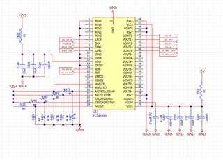
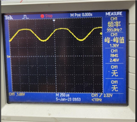
The following is the schematic and output waveform. We used the hardware working mode. Why did the output signal of 1690 go out when it clip 3V? The power supply VCC is 5V, and according to the data manual, the analog output should work up to 8VPP.


This thread has been locked.
If you have a related question, please click the "Ask a related question" button in the top right corner. The newly created question will be automatically linked to this question.
The following is the schematic and output waveform. We used the hardware working mode. Why did the output signal of 1690 go out when it clip 3V? The power supply VCC is 5V, and according to the data manual, the analog output should work up to 8VPP.


Hi Johnny,
Have you verified and confirmed the following voltages at the pin of the device and made sure they are what you would expect: VCOM, VCC and VDD
Can you plot both outputs, say Vout1+ and Vout1-, and if converting DE to SE , show that as well?
If VCOM and supplies are correct , can you apply the input to different channels and see what you get? Table 1. shows Pin Assignments in Differential Output Mode.
Have you tried sending a 0V signal in and see how the outputs look individually, assuming your VCOM is reading correctly?
Along with that can you tell me the freq of different clks .
Regards,
Arash