


Hi, TI support team
1. There is no information about LPF for anti aliasing at the ADC input terminal.
Is there an LPF inside the ADC? Or do you need an external LPF input?
2. There is no information about VQ (VCC/2) in ADC input.
Is Bias connected to the port without connecting the VCC/2 voltage on the ADC input side?
Do I have to connect the VCC/2 voltage outside the input side?
3. There is no datasheet about oversampling.
Is there an oversampling specification?
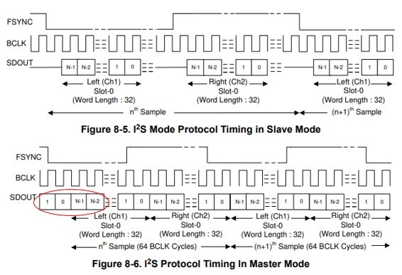
4. SLAVE mode and Master mode for I2S appear to be different.
The sdout of the slave mode seems to be common, but is the sdout of the master mode below?
Thanks.
Regards,
MJ
