This thread has been locked.

If you have a related question, please click the "Ask a related question" button in the top right corner. The newly created question will be automatically linked to this question.

TAS6422-Q1: Schematic Review Request

Part Number: TAS6422-Q1
Other Parts Discussed in Thread: TAS6422E-Q1

Hi, TI support team

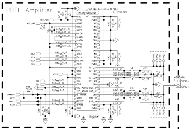
The customer used the TAS6422-Q1 to create a circuit diagram with PBTL.

Since there is no PBTL application SCH on the DATASHEET of the TAS6422-Q1, the circuit diagram was created by referring to the circuit diagram of the TAS6422E-Q1.

Please review the circuit for the PVDD power supply side and the Audio output (Filter circuit) side.

[customer's SCH - TAS6422-Q1 PBTL]

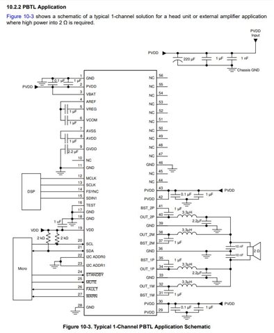
[TAS6422E-Q1 PBTL Application SCH]

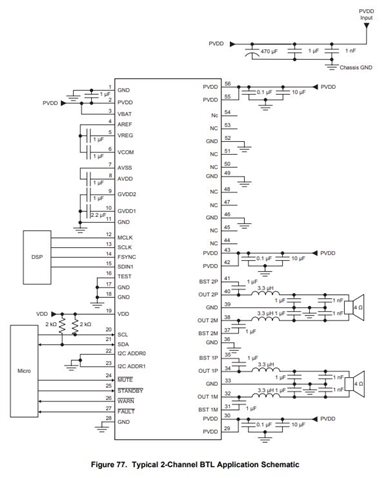
[TAS6422-Q1 BTL Application SCH]

Q. In the PBTL circuit of the TAS6422E-Q1, pins 55 and 56 are NC, but should they be treated as NC when used as PBTL in the TAS6422-Q1?

Q. Is there a possibility that a defect will occur if it is not treated with NC?

Q. Please tell us about the power sequence of TAS6422-Q1 (timing information).

Thanks.

Regards,

MJ

  • MJ,

    In response to the three questions at the end of your post:

    1. Pins 55 and 56 are not terminated internally in the TAS6422E.  In the TAS6422, they are terminated internally.
    2. In the TAS6422E no defect can occur due to connecting PVDD to pins 55 and 56.
    3. Please provide your needs for timing.  Are you using DC and AC Load Diagnostics?

    Regards,
    Gregg Scott

  • Hi, Gregg

    First of all, there is an error in relation to the circuit diagram that was first delivered.

    I am sorry.

    Among the circuit diagrams extracted from the datasheet, the BTL circuit is the circuit of the TAS6422-Q1, and the PBTL circuit is the circuit of the TAS6422E-

    Q1.

    1-1. Is the information below correct? I think it will be the opposite.

    "Pins 55 and 56 are not terminated internally in the TAS6422E. In the TAS6422, they are terminated internally."

    2-1. The PBTL circuit of the TAS6422-Q1 was created with reference to the TAS6422E.

    Is there any problem if PVDD is connected to pin 55, 56 of TAS6422-Q1?

    3-1. AC load diagnostics is the default setting and is not used.

    Thanks.

    Regards,

    MJ

  • MJ,

    1. It is correct. 
    2. PVDD should be connected to pin 55 and 56 on the TAS6422-Q1.  Not necessary on TAS6422E and will not cause a problem.
    3. Since you are using PBTL you must take special care when programming the device for PBTL mode.
      1. In typical system, PVDD and VBAT are always connected.  Keep the /STBY pin low until the 3.3Vdc is stable.
      2. Program the device via I2C while it is in standby mode.  This is necessary for PBTL operation.
      3. Pull /STBY high and the device will run DC load diagnostics.  Monitor register 0x0F until DC Diagnostics is complete and the register states it is in Hi-Z mode
      4. The device is read to be placed into Mute or Play

    Regards,
    Gregg Scott

  • Hi, Gregg

    Is there anything special about the customer's circuit diagram?

    Please review if there is a part that could be a problem in the circuit as a whole.

    In particular, please review the capacitance values of C or R in the PVDD connection part and the parts capacities in the filter part.

    Thanks.

    Regards,

    MJ

  • Hi MJ

      The schematic seems fine. Nothing special.