This thread has been locked.
If you have a related question, please click the "Ask a related question" button in the top right corner. The newly created question will be automatically linked to this question.
Hi,
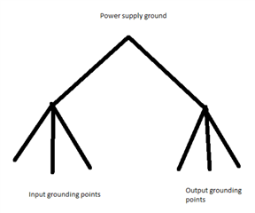
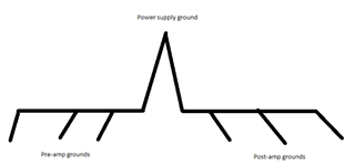
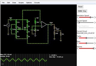
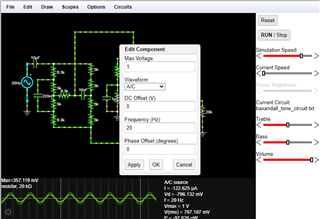
I am designing a headphone amp with a tone control circuit, with LM4808 being amp and an OPA2134 forming the tone control part. Based on layout example in LM4808, the grounds of the circuit are connected separately then joined together at the POWER GND pin. Do I have to do the same for the tone control circuits?
If I use a ground plane instead to connect all the GNDs together will it have the same effect?
Thanks
Hi Azrul,
In my experience, I haven't seen a noticeable difference between a ground plane and a star ground configuration (shown in the datasheet you mentioned) with regards to low-power applications (such as a headphone amp).
If you choose to go with the star ground configuration, you would want all grounds of both the amplifier and tone control circuits to meet at the POWER GND pin. Just be sure that there is only one path to the POWER GND for each grounding point on the board.
Let me know if you have any more questions regarding the chip or overall circuit in general. If you wish to share your layout design to this thread, I'd be happy to look it over as well.
Thanks,
Kian Fotouhi
Hi Kian,
Thanks for the reply. Is there a guideline for the type of grounding to be used? There was a Youtube video on how the groundings on a LM386 (they were daisy-chained, instead of separating input and output GNDs) affect the sound quality of the amp. Based on your response here, it seems that power output is a factor, as the LM386 can drive 8 Ohm speakers while the LM4808 can't.
I've yet to start on the layout. I appreciate if we could this thread open for about a week while I get the layout design done.
Hi Azrul,
Was this the video you watched? https://www.youtube.com/watch?v=lBGE5lwbruE
I see what he did, this is still a star ground configuration, just a bit more simplified. He's having his input (signal before amplification) grounds joining at some common point and his output (amplified signal) grounds joining at a different point. Then those two ground nodes meet at the negative power pin of the op amp. This way, the output current is never flowing on the same ground trace as the input current.
On a PCB it might look something like this, keep in mind this is a very crude drawing.
In the case of your tone-control circuit, which I'm assuming is a pre-amp circuit, those grounds can either have their own node or meet at the same point as the input grounds. You could also do some sort of daisy chain like you mentioned.
As you said, the LM386 and LM4808 differ in the loads they support, with the LM386 being able to drive as low as 4 ohms while the LM4808 only supports a minimum of 16 ohms. This means the LM386 circuit will have more current potentially flowing through the ground traces which magnifies the possibility of grounding noise.
To be safe, try a star ground approach with your circuit, but if that scheme proves to be challenging or impractical for the PCB size, I still feel that a ground plane will perform just fine. I'll certainly keep this thread open for you.
Let me know if you have any more questions.
Regards,
Kian Fotouhi
Hi Kian,
Just an update: I'm in midst of drafting out a circuit, should be be done soon. After I completed that I appreciate if you could take a quick look and see if the design is sound. I'll start the layout after that
Hi Azrul,
Thanks for the update, no worries. I look forward to seeing your design.
Thanks,
Kian Fotouhi
I think there's a mistake in the power circuitry. Could you ignore those first and take a look at the audio portion first?
Thanks
Hi Azrul,
This circuit looks good, my only concern is that the tone control circuit has a lot of gain when the pots are maxed out, perhaps try increasing the resistors on each side of the pots? I'm referring to R5, R9, R10, R11, etc.
Hi Kian,
Thanks for your advise. I've updated the schematics and fixed the power part. I've changed the location of the input caps on the power amp to precede the volume pot to remove the DC but I've added some 0Rs just in case the arrangement doesn't pan out. Do you think position of the input caps will do any difference?
Could you elaborate more on the tone control side, specifically on how to calculate the gain? So far I couldn't find any references on how to calculate the gain. The circuit is based on this here: http://sound-au.com/articles/eq.htm (Figure 5), I just modified it so that it the op amps work off a single supply.
Lastly do I need to ground all the mounting holes, or just one would be enough?
Thanks a lot for your feedback. I really appreciate it!
Hi Azrul,
Thanks for linking this article, it's really interesting. Maybe I'll use some of these circuits in my designs.
I used Falstad to model the tone control circuit, the sliders emulate the linear potentiometers for the bass and treble side. Open this text file in Falstad to see it. You can double click the AC voltage source to change its frequency in the menu.
$ 1 0.0000026041666666666666 382.76258214399064 1 5 43 5e-11 v 48 192 48 80 0 1 20000 1 0 0 0.5 c 48 80 96 80 0 0.00001 -2.4998116187541717 0.001 w 128 80 240 80 0 a 368 128 448 128 8 15 -15 1000000 2.4999690238244923 2.500000000006164 100000 R 320 64 336 64 0 0 40 5 0 0 0.5 r 320 64 320 144 0 100000 c 288 144 288 224 0 0.000001 2.500000000006164 0.001 r 320 144 320 224 0 100000 g 320 224 320 240 0 0 w 288 144 320 144 0 w 288 224 320 224 0 g 48 192 48 224 0 0 w 320 144 368 144 0 r 128 80 128 128 0 6300 r 128 128 128 176 0 5000 r 128 176 128 224 0 5000 r 128 224 128 272 0 6300 r 128 176 192 176 0 6300 c 192 176 240 176 0 1e-8 -9.015010959956271e-14 0.001 r 240 80 240 112 0 5000 r 240 112 240 176 0 5000 r 240 176 240 224 0 5000 r 240 224 240 272 0 5000 w 240 272 128 272 0 w 192 176 192 -16 0 w 192 -16 368 -16 0 w 448 128 448 320 0 w 448 320 240 320 0 w 240 320 240 272 0 w 368 -16 368 112 0 w 128 128 80 128 0 c 80 128 80 224 0 2.2e-7 0.004540025657168378 0.001 w 128 224 80 224 0 w 96 80 128 80 0 c 448 128 512 128 0 0.000001 2.499595520784713 0 r 512 128 512 192 0 1e-9 g 512 240 512 272 0 0 r 512 192 512 240 0 100000 r 576 192 576 256 0 20000 g 576 256 576 288 0 0 c 512 192 576 192 0 0.000001 -0.0003159441905263849 0.001 o 38 64 0 4099 2.5 0.0001953125 0 2 38 3 38 20 F1 0 10000 0 -1 Treble 38 14 F1 0 10000 0 -1 Bass 38 35 F1 0 100000 0 -1 Volume 38 37 F1 0 0 100000 2 \0 38 15 F1 0 0 10000 1 \0 38 21 F1 0 0 10000 0 \0
In the article you linked, it mentions that the standard boost and cut range for either frequency band is around +/- 15 dB, which from a voltage standpoint is pretty extreme (a 5.62 voltage gain). My worry is that an extreme adjustment will clip the input of the headphone amp.
I also changed the resistor values around the tone pots so that the gain for each control is around +/- 6dB. This will certainly be audible but not extreme enough to clip the amp, I believe.
Also, with a 10k volume potentiometer and the 390nF capacitor at the tone control output, your low frequency performance may suffer. In the attached circuit model, I changed the volume pot to a 100k linear and the capacitors to 1uF and now frequencies down to around 40hz have unity gain. You would obviously want to keep the log taper, I just couldn't model it easily in Falstad.
As far as mounting holes, you can place a pad on each mounting hole where it will connect to the chassis via the screw, but only create a trace to the PSU ground from the nearest mounting hole. This will ground the metal on the mounting holes through the chassis (so they won't act as antennae) but will avoid a ground loop since any current will only flow through the one mounting hole to ground.
Let me know if you have any more questions. This is a really interesting design so far, great work.
Thanks,
Kian Fotouhi
Hi Kian,
Thanks for the compliment. I've built some audio amps before but never on a pcb so this is my first foray into the unknown, so to speak.
I tried Falstad but I can't make any sense of it so I'll look into it later on. In any case once I get the layout done I'll play put some pads during the layout phase so that I could try different resistor combinations.
There's a mistake on the tone control circuit, it's missing a 220nF cap on the bass side, I noticed it as your Falstad model has it. As for the 10K volume pot, I had trouble sourcing a stereo 100K pot, for that reason I settled on 10K pot as most of the electronic suppliers over here (element14, mouser,etc) have it, plus the 100K pot is quite expensive as well. Actually the input cap value isn't 390nF, but 330nF as I thought it's a compromise between 270nF and 390nF when the pot is at min and max (the calculations are detailed in the schematics).
Any thoughts on using USB-C as a power source? My concern is the USB noise being coupled into the audio line; I saw some articles mentioning some sort of ferrite bead to filter the power line.
Finally, any suggestions for the caps? the datasheet mentions that the caps types will influence the sound quality; I was thinking of ceramic for those in nF range, and either tantalum or electrolytic for uF.
Thanks again for all of these, you have been a great help
Hi Azrul,
Sorry Falstad wasn't working for you. Here's a screenshot of how it should look.
If you double click the AC source, you should see this menu where you can set the voltage and frequency.
The sliders on the right (Treble, Bass, Volume) emulate the pots. The plot shows voltage in green and current in yellow.
I found many two gang 100K log pots on mouser, for example:
PDB182-K230K-104A Bourns | Mouser
Maybe they aren't available in your country which is unfortunate.
With the 10k pot and 330nF capacitors, I couldn't get a unity response at 60 Hz until I nearly maxed out the bass tone knob. If you don't necessarily care about bass response below 80 Hz then it's no issue. Just a design consideration I wanted to share.
When you say you calculated the capacitor values based on the pot position, what calculation were you performing?
Ferrite beads are generally good for filtering high frequency noise in lower power applications like this, so you could definitely include one in this design.
For capacitors, I've had great results with film capacitors for the audio signal and electrolytics for power/bulk purposes. Tantalum capacitors are quite expensive compared to both film and electrolytic, and I think film caps will provide better performance than a ceramic.
Looking forward to hearing from you,
Kian Fotouhi
Hi KIan,
For some reason scope part of Falstad didn't appear like the one you have, mine had the signals packed together that I couldn't pick them apart. I'll check them out later to see if I could get them working like yours.
I'm based in Malaysia, and from the searches in Radiospares and element14 the choices were quite limited. Digikey got a few but the delivery charges are very high. There are a lot more choices from the local online stores but I am not sure how good these pots are and they don't have any documentation.
I used the guide in the LM4808 to determine the input capacitor values, and substitute R = 0R when the pot is at minimum and 10KOhm at max
Thanks
Hi Azrul,
I found this pot from Tayda, they're based in Thailand. I've ordered from them before and haven't been disappointed with the results in my own audio projects. Alpha manufactures this one and they make good quality products.
The issue is that the volume pot makes it much harder to calculate the cutoff frequency. Along with caps C17 and C6, you're creating a pretty complex second order filter where the cutoff frequency varies greatly with the pot. My first suggestion is removing the cap after the pot. My second suggestion is using a 100k pot, since further increasing the capacitance instead of resistance would introduce more startup pop.
I calculated the transfer function of your circuit and plotted the magnitude response with the -3 dB cutoff marked. This is the response of your current circuit.
With a 100k pot rather than 10k, this is the new transfer function.
Removing C6 and changing C17 to 470nF yields the following response when the pot is at full volume.
With this configuration, low frequency performance is preserved at half volume.
Even at 10% volume, the cutoff frequency is still decent.
Let me know what you think of these changes. If you leave the 10k pot, you'll need to increase C17 considerably to gain low end performance, but this will cost you in terms of adding startup pop. I would still suggest removing C6 as it seems unnecessary.
Hi Kian,
Thanks for your suggestions, I'll incorporate them into my layout.
One thing to note though that I am not going to mount the two input capacitors together, it's either one or the other but not both. In the example you gave, C17 and C6, in the schematics C6 is marked as DNM - "Do Not Mount". I put the pads in advance so that I can swap the setup easily.
The tone control pots are linear, correct? Only the volume pot is log type? Also what software do you use for the curves above?
I think I getting quite close to the end for the schematics part. I just need to finalise the parts footprint before starting the layout.
Oh okay, that makes a lot of sense now. Thanks for clarifying. In that case, those simple modifications may be worthwhile.
The tone pots being linear should work fine, the most important thing would be for the volume to be log. I'm sure any kind of pot would work okay for the tone controls. For the above curves, I used MatLab to calculate and graph the transfer functions
Hi Kian,
I've completed the 1st draft of the layout. Sorry it took a while, some other issues came up that needed my attention.
I am not sure what type of files you need to check the layout, for now I've uploaded the gerber files. I am using Kicad 7.
Track width used is approximately 10 mils for both signal and power. GND planes on both top and bottom layers.LM4808_hp_amp_gerber.zip
Hi Azrul,
I'm glad you were able to get the layout drafted. It looks good to me and I don't notice any obvious problems.
Let me know if you have any additional questions.
Thanks,
Kian Fotouhi