This thread has been locked.

If you have a related question, please click the "Ask a related question" button in the top right corner. The newly created question will be automatically linked to this question.

TAS5414A bad output signal

Other Parts Discussed in Thread: TAS5414A, TMS320F28335

Hi everyone,

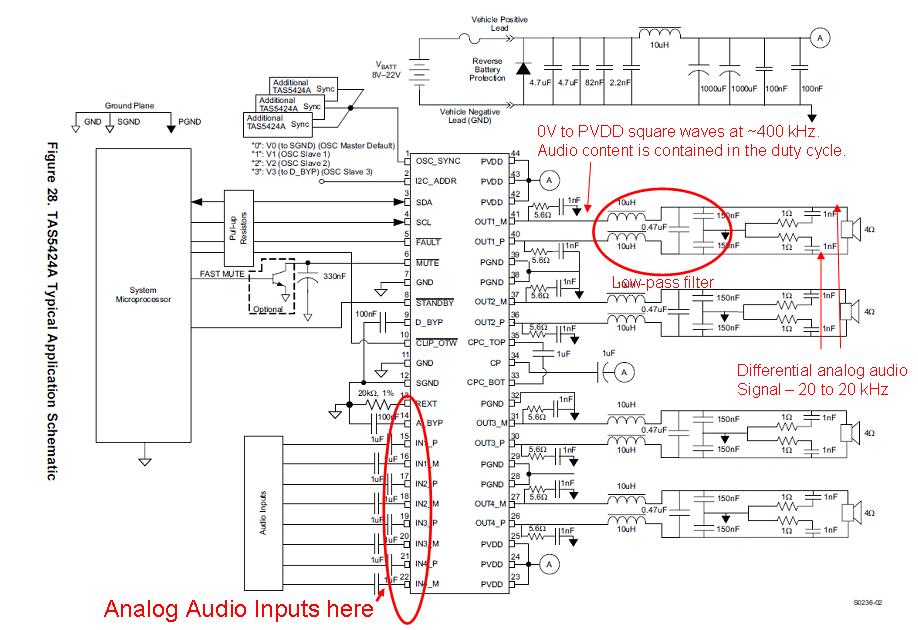
I have problem with output signal of amplifier based on TAS5414A. My circuit is identical with TAS5414A evaluation module. Supply voltage is 15V. I have my circuit conect to PC with USB to I2C interface from Evaluation module. Before output inductor is rectrangle signal with duty 1:1, frequency about 400kHz and amplitude about 30Vpp. This output signal is independent of amplitude and frequency of input signal.

Where is problem? Help me...

Have somebody similar problem?


PS: sorry for my english :)

  • Pavel,

    The TAS5414A is a Class-D amplifier, meaning the output takes advantage of pulse width modulation (PWM). 

    Basic operation of a class-D (PWM) amplifier:

    1 ) First the input is compared to a triangle waveform

    2) If the input signal is greater than the triangle waveform than the output is high.  If the input signal is lower than the triangle waveform than the output is low. 

    3) From the comparison in 2, the output appears as a set of pulses (the rectangular waveform below) which represent the energy under the sine wave.

    4) Finally, an output filter is added to remove any harmonics created by the square wave switching.  This filtered waveform will appear as a sine wave to the speaker. In audio this means all signals above ~24 kHz are removed.

    The diagram below delineates this process.

    Also see the link below for PWM in action.

    http://www.falstad.com/circuit/e-classd.html


    To create a sine wave with a digital signal (the two level PWM signal), the amplifier varies the duty cycle which is the ratio of high to low signal over one period. The 1:1 or 50% duty cycle waveform you are seeing at the output simply means there are either no inputs applied or the amplifier has been muted.  When the PWM amplifier is muted it produces a 50% duty cycle which creates an average power of 0.

    Let me know if this helps and if you have any more questions.

    Thanks,
    Brian


    Graphic from - http://en.wikipedia.org/wiki/File:Pwm.png

  • Hi Brian,

    I've been searching for a method to generate the sine-triangle pwm as you described using the ezdsp f28335 series. The epwm manuals of the dsp don't have sample codes for this so can you please share the code to generate a sine pwm. Thanx 

  • Shoaib,

    The explanation I provided was to illustrate what the audio amplifier output would look like; however, the PWM signal is created within the audio amplifier.  DO NOT try to create the triangle wave.  You simply need to provide an analog audio signal to the inputs.  The analog signal can be in the range 0-1 Vrms depending on the gain settings (see datasheet page 9). 

    Input signal (you provide these)  --> PWM Conversion and amplification (inside amplifier) --> PWM Output (at the amplifier outputs)

    -Brian

  • Shoaib,

    Maybe this figure will help. I took Figure 28 from the data sheet and tried to describe the signals at different nodes.

    -d2

  • Hey Don,

    the sine-triangle comparison Burk provided for generating the pwm is exactly what i need - just having a hard time coding for it since the CCS didn't have any sine pwm sample projects/codes and I don't have much of an experience programming the ezdsp. I actually need the sine pwm for an H-bridge single phase inverter and not an audio application but that doesn't really matter. The device I'm using is the ezDSP TMS320F28335.

    It'll be great if you can help me out and provide with an algorithm of sorts which I can follow and code for a sine-triangle pwm. I have downloaded the signal generation library but dont know how to use it exactly (poor documentation) with the code composer studio. Are there any samples/examples available for generating a sine pwm?

    PS - Overwhelmed........Helpppp. 

  • Hi, Shaib,

    So I guess you're not actually using he TAS5414A, then?

    You are trying to duplicate its functionality using a DSP?

    I apologize, but I have no idea about any of this, I work in our audio amplifier group.

    I am not sure if we have a more appropriate forum where you might ask your questions of our DSP guys. (ah, life in a huge company!)

    What about the CCS forum: http://e2e.ti.com/forums/default.aspx?GroupID=25 ?

    -d2

  • Thank you Brian. I had two stupid problems :) First, TAS5414A was in hardware mute (pull down resistor on mute pin). Second, output filter inductor was connected incorrect. Half of inductor was connect "anti-bifillar", then induction was zero. When I have solved this problems, the function of amplifier is OK.

  • Pavel,

    Glad to hear you were able to get it to work.

    Brian