


Dear TI experts,
My customer now tests their own PCB with TAS6422E-Q1.
First they applied 3.3uH for the inductors below. (L38, L39, L40, L41)
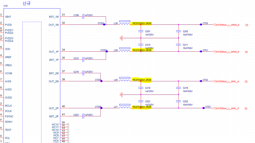
They found that there is a sine wave with some noise, and they changed the value of inductors from 3.3uH to 10uH. then the sine wave is much more clear.
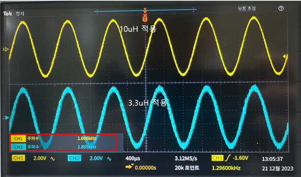
(Yellow waveform is applying 10uH, cyan waveform is applying 3.3uH.)
- Is it ok to use 10uH in this situation?
- What is difference between 3.3uH and 10uH?
And I have one more question.
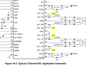
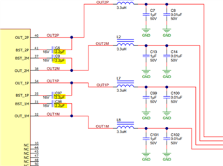
- There are different inductor value between datasheet and EVM schematic. which one is right?
Best regards,
Chase
