Other Parts Discussed in Thread: TAS2505
Hi Expert,
My customer Bosch is using TAS2505-q1 for quite a long time. We are setting bench to test the THD+N EVM on analog input mode and digital input mode.
- Analog Input
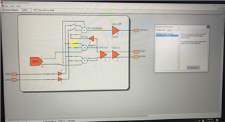
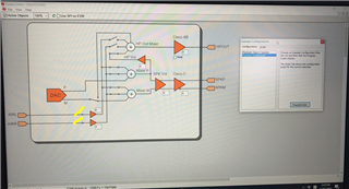
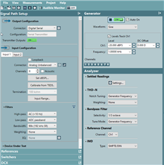
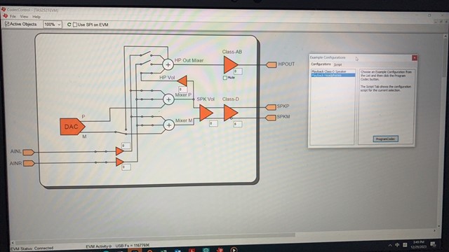
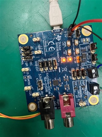
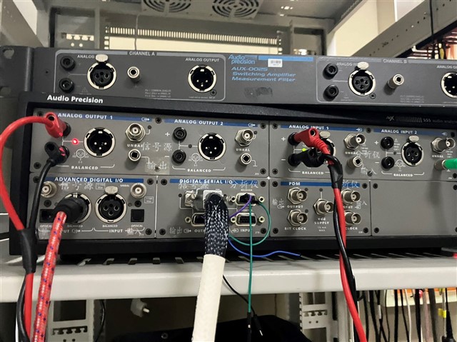
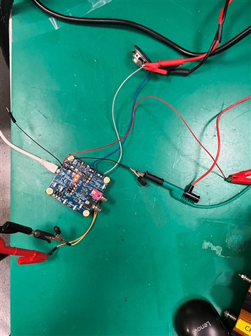
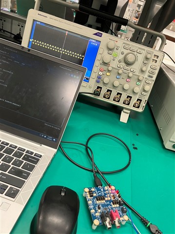
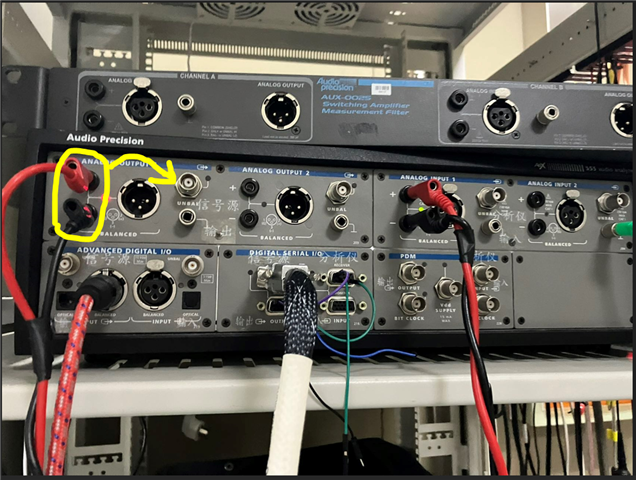
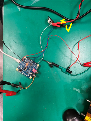
I do the test on analog input mode. However, it seems the set up of AP is wrong. You can see the AP set up and Bench set up below. 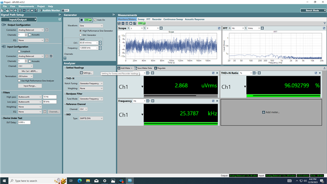
It seems that there is no output. I am so confused. The i test the PWM on P+ and P-. There do have PWM.
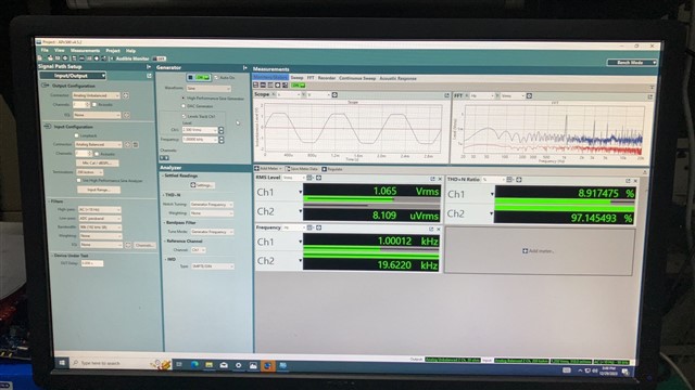
Then I change the set up of AP. I change the AP output from balance to unbalanced( I change the wire on AP too, but i didn't take the photo) What's more, i just connect 1 line P- to AP input. The i get the THD+N, but it seems that the value is too large.
Then the 2 channel all have PWM wave form. But it seems that the waveform are all the same. Because when i connect the P+ and P- to AP analog input, there is no output.
- Digital Bench test
My customer bosch test the digital input. The AP output is digital serial and AP input is AP unbalanced. Customer didn't use the GUI. They key in the register. You can see the attached.
However the result is shown below:
Vout=1.4V
No load : THD+N 0.05%
4ohm:THD+N 1.2%
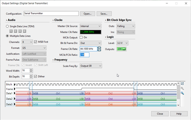
The I2S serial configuration is shown below.
All in all, would you mind sharing with me the AP THD+N test project for TAS2505-Q1 analog input and digital input? If the AP/ HW/ GUI set up are not correct, could you please point out any specific errors?
Thanks a lot!
Kind Regards
Imelda