This thread has been locked.

If you have a related question, please click the "Ask a related question" button in the top right corner. The newly created question will be automatically linked to this question.

TLV320DAC3101EVM-U: TLV320DAC3101EVM-U

Part Number: TLV320DAC3101EVM-U

Hi,

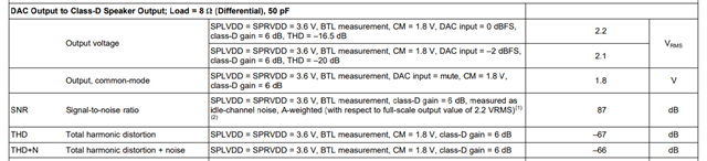
We are using TLV320DAC3101EVM-U and testing the part for different AC parameters like SNR, THD etc.

We have below 2 questions:

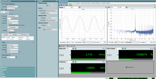
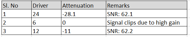
1) With the default configuration on GUI, the Driver gain is 24dB and Attenuation is -29.3 dB. But with full scale range of 5V, we were not getting exact output voltage but when we change attenuation to -28.1, the output is fine. Just wanted to know the rationality for this.

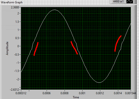
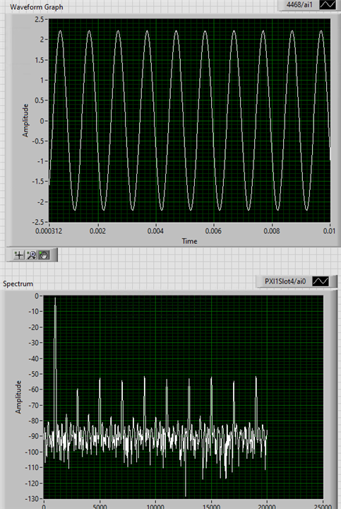
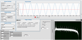
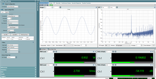
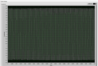
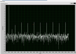
2) When we try to plot the FFT of the acquired signal from the Eval board, we see there are harmonics on the plot. Could you please help us on removing these harmonics or let us know what could we look for. Attached below screenshot of results in both Time domain and Frequency domain.

Let me know for more inputs.

  • Hi Kiran,

    Regarding question 1, do you mean the output was not exactly 5V at full scale digital input signal? So slightly lower amplitude?
    It may just be how gain and attenuation add-up, you may start by setting both to 0dB, and adjust from there.

    Can you expand the time domain view of the waveform? Does it look distorted in any way? If you have a load connected, could you disconnect and check the signal again, is there any difference?

    Best regards,
    -Ivan Salazar
    Applications Engineer

  • Hi Ivan,

    1) Right, the output was slightly lower than expected full scale. by changing attenuation, output is fine. Just wanted to know which is correct attenuation value to be used, as we have adjusted now by testing. 

    2) We have used the default configuration of the EVM like MCLK (11.2896 M), BLCK 2.8224 MHz and WCLK 44.1 KHz all from external source. Please find below zoomed image of time domain.

  • Hi Kiran,

    1. Understood, the output voltage drive would also depend on the load impedance, so it should be OK for you to fine adjust it through testing.
    2. Thanks for the additional captures, I'll check this on my side and provide further comments tomorrow or early next week after some testing on my side.

    Best regards,
    -Ivan Salazar
    Applications Engineer

  • Hi Ivan,

    Any update on above case.

  • Hi Kiran,

    I've setup the EVM on my side and measured the Class-D output, the harmonics from your capture seem expected, the THD+N performance should still be within expectations:

    Best regards,
    -Ivan Salazar
    Applications Engineer

  • HI Ivan, 

    Thanks for checking this and your response.

    We did perform some measurements with the acquired signal (We played a .wav file on PC with 0dBFS and measured Analog output on DAC), below are the results and SNR is around 62dB and THD+N is around 55. We have optimized setup the best possible way. Could you please review below results and let us know for any suggestions.

  • Hi Kiran,

    What kind of filter are you using to measure the Class-D output signal? What is the bandwidth of the measurement tool being used?
    Can you also check if you have any audio enhancement effects from your PC running through the EVM? Perhaps that's adding non-linearities.
    For my test I generate and play a 1kHz sinewave using Audacity.
    I don't see major difference, but you could try changing the gain/attenuation settings:

    • Set Class-D Speaker Driver to minimum 6dB
    • Set Analog Attenuation to 0dB
    • Then you can fine adjust gain to 12dB or 18dB and reduce attenuation to keep the output from clipping.

    Best regards,
    -Ivan Salazar
    Applications Engineer

  • Hi Ivan,

    Please find my below responses.

    Filter-> A -weighting filter

    BW-> 20Hz to 20KHz

    We also played from Audacity. I tried below configurations:

    Could you let us know the SNR value you have observed. Also kindly let us know if we can schedule a call to discuss on same.

  • Hi Kiran,

    I'll setup the test again and share further details tomorrow by the end of the day.

    Best regards,
    -Ivan Salazar
    Applications Engineer

  • Hi Kira,

    Quick update: couldn't test this today, I'll come back with the results tomorrow.

    Best regards,
    -Ivan Salazar
    Applications Engineer

  • Hi Kiran,

    After testing I noticed that for previous result, I used DAC3120 instead of DAC3101, the maximum output voltage drive is lower for DAC3101.

    Now testing with DAC3101, I get SNR of ~84dB:

    I repeated the THD+N capture with the proper device, just before clipping (output reaches maximum ~4Vpk)

    Datasheet has THD+N plots showing the minimum THD+N level at about -65dB, although this is at slightly lower output power level.

    Best regards,
    -Ivan Salazar
    Applications Engineer

  • HI Ivan,

    Thanks for checking this, appreciate your response.

    Our setup details:

    1) 1KHz, -1 dB sine wave played from Audacity.

    2) Driver: 24 dB, Attenuation: 28.1 dB, 8 Ohm Differential load connected across speaker output, A -weighted Filter. 

    3) We do see similar THD+N value of: -55 dB, and our SNR is around 62 dB. As per below screenshot from datasheet, since there is no minimum value. Is the value observed acceptable. 

    3) Board details for reference:


    Let us know if we can schedule a call to discuss the same.

  • Hi Kiran,

    I'll reach out to you offline to setup a time for the call.

    Best regards,
    -Ivan Salazar
    Applications Engineer

  • Sure, please send an invite so we could discuss on call.

  • I've sent an email, let's sync offline.

    Best regards,
    -Ivan Salazar
    Applications Engineer