Hello everyone,
We are currently experiencing overcurrent troubles with the TAS5806M used in mono mode (PBTL) with a 4Ohm speaker.
We had already used this component successfully with an earlier proto board, where we were able to play sounds and modify the volume. In this new configuration, the schematic and program are a direct copy of the previous version, in fact only the layout has been modified.
The overcurrent occurs after initialization, when the DEVICE_CTRL_2 register is written to configure the device state control register in PLAY mode.
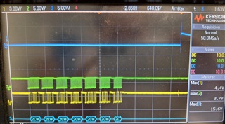
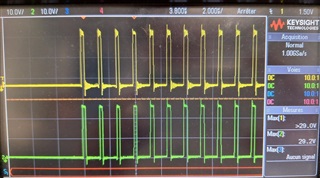
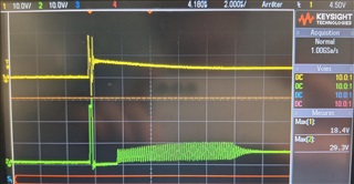
At this point, a 200ns pulse is heard in the loudspeaker, and the CH1_OC_I (Left channel over current fault) bit is set to H in the CHAN_FAULT register.
As a result, no sound can be played. The OUT_A and OUT_B outputs are shown below, PVDD = 24V.
The init function of the device:
void TAS5806M_Init(void)
{
	HAL_Delay(10); // wait at least 5 ms from PDN set to 1

	// Reset
	TAS5806M_SetRegister(TAS5806M_REGISTER_RESET_CTRL, 1 << 4 | 1 << 0);
	TAS5806M_SetRegister(TAS5806M_REGISTER_RESET_CTRL, 0);

	// Reset DSP
	TAS5806M_SetRegister(TAS5806M_REGISTER_DEVICE_CTRL_2, (1 << 4) | 0x02);
	TAS5806M_SetRegister(TAS5806M_REGISTER_DEVICE_CTRL_2, 0x02);

	// PBTL (mono)
	TAS5806M_SetRegister(TAS5806M_REGISTER_DEVICE_CTRL_1, TAS5806M_REGISTER_DEVICE_CTRL_1_VALUE);

	TAS5806M_SetRegister(TAS5806M_REGISTER_SAP_CTRL1, 0); // 16 bits
	TAS5806M_SetRegister(TAS5806M_REGISTER_DIG_VOL_CTRL, 10); // 24 - 0.5 * N dB => -15 dB for 78

	TAS5806M_SetRegister(TAS5806M_REGISTER_AGAIN, 0x0); // 0 dB

	TAS5806M_SetRegister(TAS5806M_REGISTER_SAP_CTRL3, 0x10);

	HAL_Delay(10); // wait at least 5 ms
}
The schematic:
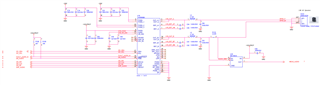
We are wondering whether the problem is with the electronics or the software. The IC has been replaced, but the fault still exists.
Does anyone have any suggestions? Any feedback would be appreciated!
Thanks
EL