This thread has been locked.

If you have a related question, please click the "Ask a related question" button in the top right corner. The newly created question will be automatically linked to this question.

TAS6422-Q1: Amp output random mutes at high power

Part Number: TAS6422-Q1

We are bench testing our custom TAS6422-Q1 board. We are doing power / heat tests by playing 1KHz sine waves via TDM, with the amp outputs connected to 100w 4R resistors.

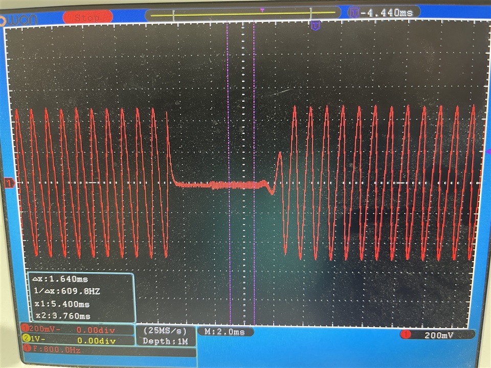
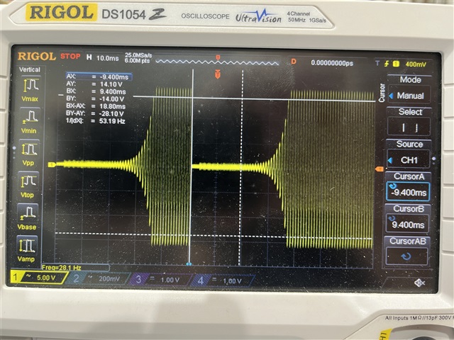
At lower amp gains everything is good, we get an excellent low distortion sine wave at the amp outputs. However, once we go above about ~25w output power (about -2.5dB @ gain 4 it seems), the output starts rapidly and randomly "muting" or silencing (see attached image). This happens one or time times a second usually, for just very brief moments (a few tens of milliseconds). 

Note we have the other channel at -9dB, and are only monitoring one channel for now. Both channels have 4R loads attached. Temperatures are all good (40-50C), the part is well heatsunk. 

Here's the thing: We are monitoring all the amp diagnostics registers, and we see no alarms. Power rails appear to be good, although we will 'scope those tomorrow to double check. We have other items on the same power rails (eg; the MCU generating the TDM), and that exhibits no issues. We have tried 2 different power supplies, both of which are >8A. Current draw is around 2A @ 24v.  

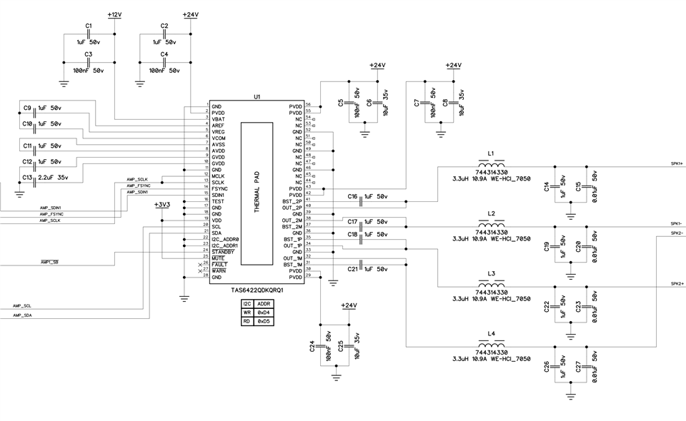
I have attached our schematic which should explain the design. Is there anything we're doing wrong? Much appreciate any help. We will work on this again tomorrow, and update if we find anything interesting. 

  • Still no luck from our tests today. The 24v power rail seems okay. We did try increasing the Volume Rate parameter, and we see this on the scope now:

    Again, this rapid random muting only occurs when >25w output power. 

  • Hi Martin 

       Could we have a try testing at device's OUT pin to GND? I want to check if the output PWM is totally stops or not.

       If there's no PWM, then should be some FAULT been triggered, and the register supposed to tell us something. Could we double confirm the register value in 0x0F to 0x13, when the FAULT been triggered.

  • Hi Shadow

    I'm Martin's programmer working on this problem. Some updates:

    My mistake, there is in fact an Invalid Clock fault we are getting in register Global Faults 1 (0x11). We are quite often seeing the Invalid clock fault above 25w, and it seems to coincide with when we see this muting.

    In the manual, Section 9.3.1.6 says: "When any kind of clock error, MCLK-FSYNC or SCLK-FSYNC ratio, or clock halt is detected, the device puts all channels into the Hi-Z state. When all audio clocks are within the expected range, the device automatically returns to the state it was in." This pretty accurately describes the behaviour we're seeing. This is leading me to believe this is the source of our problems.

    However what's confusing is that we only see this invalid clock fault at >25w output power. Below that, and it seems to consistently work reliably, and we don't see the invalid clock fault.

    I am also not sure where the fault is in the clock. We are using an ADAU1401 DSP that I believe I have correctly setup to clock out TDM data. Given that we have no issues below 25w suggests that the clock settings are mostly okay, otherwise I would suspect we would hear a lot more artefacts.

    My only cause for concern is Section 9.3.1.4 TDM Mode in the manual, in which it is stated: "If SCLK and MCLK are connected together than FSYNC should be minimum 2 MCLK pulses long." In the schematic Martin sent above, you can see our SCLK and MCLK are connected together. 

    However in the ADAU1401 manual, Table 48 under 2078 (0x081E)—SERIAL OUTPUT CONTROL REGISTER, the bit for the frame sync says: "Frame Sync Type. This bit sets the type of signal on the OUTPUT_LRCLK pins. When this bit is set to 0, the signal is a word clock with a 50% duty cycle; when this bit is set to 1, the signal is a pulse with a duration of one bit clock at the beginning of the data frame."

    This "one bit clock" is slightly concerning, as it seems the TAS6422 wants 2 bit clocks. However again, below 25w, everything seems to work correctly. 

    Any advice or thoughts?

    Many thanks,

    Daz 

  • Hi Daz

      It's strange that seems my previous reply is disappeared. Could you please have a try with 50% duty cycle of FSYNC clock? If it helps, I would explain more. Thanks.

  • Hi Shadow,

    Great shout! I've just tried as you suggested, switching frame sync type output by DSP from a pulse to an LRCLK with 50% duty, and that seems to have solved the Invalid Clock alarm, and solved the muting issue!

    Any additional explanation would be very welcome. However your assistance has been incredibly appreciated. 

    Many thanks,

    Daz

  • Hi Daz

       Sure. Actually I tried to explain here yesterday, but that answer disappeared somehow...

       In the datasheet there's a statement as below, so not supposed to connect MCLK and SLCK together. The E and R version of TAS642x devices fixed this problem and removed this statement. The other TAS642x device suggest to follow it.

      When MCLK and SCLK sync in phase, not always cause problems, need certain combination including TDM, 1bit FSYNC, and high power. Seems we triggered them all.