Hi team,
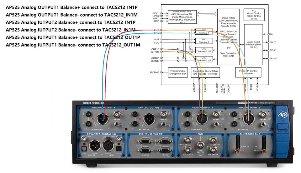
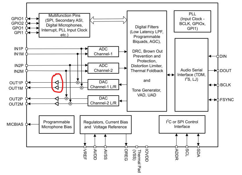
Could you help check the if the red marked is a non-inverting buffer or inverting output buffer?
Thanks and Best regards,
Will
Hi team,
Could you help check the if the red marked is a non-inverting buffer or inverting output buffer?
Thanks and Best regards,
Will