TAS2781EVM: I2S left justified format

Part Number: TAS2781EVM
Other Parts Discussed in Thread: TAS2781,

Tool/software:

Hi,

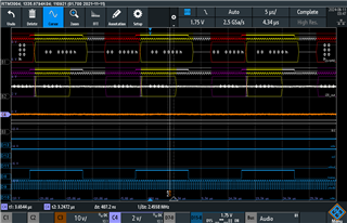
Im preparing the interfacing of I2S to this nordic micro nrf5340 to the TAS2781 evm. at this moment I can only configure the micro I2S with the frame and sbclk below scope format.

Now, if I hook up my scope with just the 2781evm, the xmos channel i2S is default configured to TDM, where the frame signal inhibit for one sbclk cycle at the start of the comms only and at the end of the last bit depending on the channel number. I was trying to find a way to configure xmos to communicate similar to my micro that I intend to use but with no success.

my question are

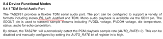
  • does the tas2781 would be compatible with the i2S format scope capture below? I have attached a section in the datasheet that it should be possible but I just want to confirm as I didn't see any setting in the PPC3 control panel to make this I2S configuration.
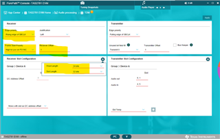
  • can I change xmos TDM format to be similar to the waveform below?. This way I can iterate on the correct configuration using the EVM and PPC3 and do an extract of the final i2C config header file to be used in my code.?\

Note: at this moment I have just hook up the i2c line of my micro to the 2781(working fine), Once I hook up the i2S between the boards, i will loose the PPC3 interaction with the 2781evm. which will make this thing difficult to debug..

  • Hi Jose, 

    Yes, the TAS2781 will work with those I2S clocks. 

    It appears to be 48 SBCLK/FSYNC. 48kHz FSYNC so SBCLK clock should be 2.304MHz, correct? And data bits latched on the rising edge of the SBCLK. 

    If the yellow and red highlights in the scope shot are supposed to be the left and right channel data there may be some concern. Standard I2S will define the data bits to start 1 SBLCK cycle after the rising and falling edge of the FSYNC. however this can be configured in the register settings to be 0,1,2 SBCLKs etc.

    you wont be able to reprogram the XMOS. here is what i would do;

    Setup the EVM, Microcontroller, and PC such that the I2S is coming from the microcontroller -> TAS2781EVM , and I2C is coming from PC -> TAS2781EVM. in this way you can quickly iterate and change settings and view any interrupts using the PPC3 GUI.

    also, by the default register settings TAS2781 will be configured to automatically detect your FSYNC and SBCLK/FSYNC Ratio, and since you are using common values there should be no issue

    You may need to configure the following settings manually in your system, for example your slot length will be 24 and word length will be something equal to or less than 24

    edge polarity; what edge of SBCLK is the data latched on

    Frame start polarity; what edge of FSYNC is defined as the frame start

    Receiver offset; how many SBCLKs between frame start and data start (I2S is defined as 1)

    Best regards,

    Arthur

  • yes the SBCLK clock is at ~2.3Mhz for 24bit 2 channel setup..

    I will try today your debugging/configuring suggestion and see how it goes.

    thanks for looking into this btw. I appreciate the quick response.


  • Hi Jose, 

    let me know if you are able to get it working.

    Regards,
    Arthur

  • Hi Art,

    I have followed the setup that you suggest, and I was able to configure the 2781 to accept the i2s left justified in the i2s communication. thank you very much.

    Im now trying to decode the I sense data from 2781 using the micro.. at the moment my buffer is a combination of left and right data. Im trying to filter the current data. everything is looking good..

    thanks for the support

    Jose