This thread has been locked.
If you have a related question, please click the "Ask a related question" button in the top right corner. The newly created question will be automatically linked to this question.
Tool/software:
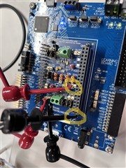
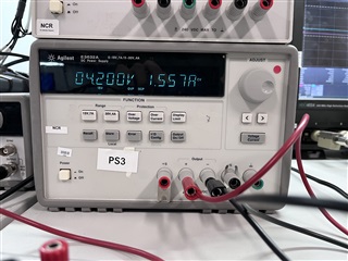
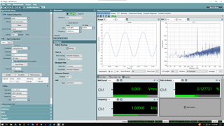
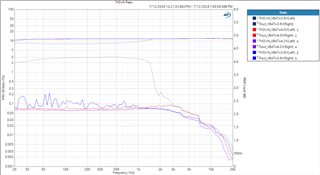
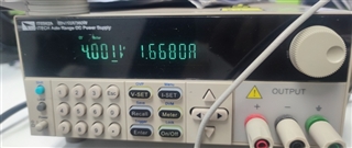
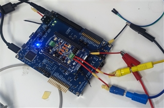
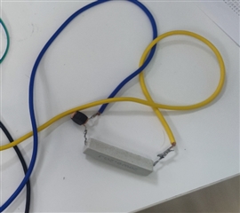
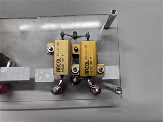
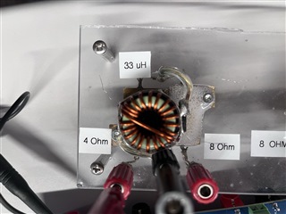
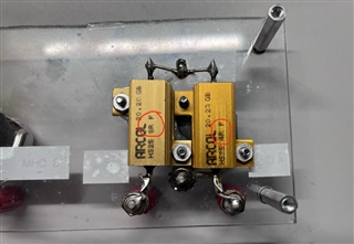
test environment: PPC3-EVM-MB+TAS2562-EVM-DC Load: 8ohm+33uH input: 1K@0dBFS sine wave DC_power_Suply: 4.2V@10A
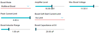
the default value of 2562 controlled by PPC3 is not adjusted
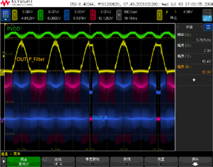
When VBAT below 4.2V,It was found that PWMP and PWMN have a probability of no output, and at this time, the PPC tool did not report any abnormal irq
1. If the output amplitude is adjusted to -0.5dBFS, PWM will be relatively stable and there will be no abnormalities.
2.There will be no abnormalities when VBAT is 5V
3 When the frequency is lower, there are more anomalies, but when the frequency is higher, the probability of anomalies is relatively small
Hi Gan,
Are you applying 4.2V into PPC3-EVM-MB on J12/J11? Or directly to TAS2562-EVM-DC by removing the VBAT jumper?
Please note that PPC3-EVM-MB is rated only down to 4.5V. If you need to supply lower voltage you need to provide 5V as you normally do, then remove VBAT jumper on TAS2562 EVM and connect the external supply to the pin going to the IC.
Best regards,
-Ivan Salazar
Applications Engineer
Hi Gan,
No special configuration should be needed for lower supply voltage, although you may try disabling features like brown-out protection (if enabled).
I'll double check on my side and come back to you soon.
Best regards,
-Ivan Salazar
Applications Engineer
Hi Gan,
I was able to test with default settings and 4.2V battery connected directly to VBAT. Please refer ot the below captures:
Best regards,
-Ivan Salazar
Applications Engineer
Hi Gan,
I'm using a 8Ohm+33uH load.
I'll setup the test and get back with the results by tomorrow afternoon.
Best regards,
-Ivan Salazar
Applications Engineer
Hi Gan,
Attached is the test result:
One special note on VBAT=3.6V: The default settings will have higher THD+N as shown in the dimmed dark-blue curve. After increasing the boost limits as the below PPC3 capture, the performance improves as shown in the bright-blue curve (around 0.1%).
Best regards,
-Ivan Salazar
Applications Engineer
hi ,Ivan,please take a photo of your load.
if you use default setting to test,maybe the difference is our environment just like DC power/load or others
Hi Gan,
I'll take a photo and share tomorrow.
Best regards,
-Ivan Salazar
Applications Engineer
Hi Gan,
We use these resistor/inductor loads, connecting to the 8Ohm side has the two 4Ohm resistors in series.
Best regards,
-Ivan Salazar
Applications Engineer
In your picture,it seems your load is one 8ohm and one 4ohm connect in series,so your test load is 12ohm?
in fact i also bought a few 2564 EVM,i find it under the condition of VBAT of 4V, the performance of 0dBFS is very poor,THD+N only have 5%,there is a significant difference from the 0.1% described in your datasheet.
Hi Gan,
That's correct, I described this wrong. 8Ohm connects 8Ohm resistor only. 4Ohm only connects 4Ohm. There's no case with both in series.
Please refer to this previous post, VBAT = 4V still has THDN <0.1%: (+) TAS2562YFPEVM-DC: PWM waveform abnormality when TAS2562 outputs 0dBFS - Audio forum - Audio - TI E2E support forums
Perhaps you can try setting the boost current limits as I suggest there as well.
Best regards,
-Ivan Salazar
Applications Engineer