PCM6260-Q1: Abnormal on output data

Part Number: PCM6260-Q1

Tool/software:

Hi team, 

Customer met some problems for PCM6260-Q1. You can find the details as below. Please help provide some suggestions. 

Besides, do we have purepath tool that can help on this debugging? I shared this one(https://www.ti.com.cn/tool/cn/PUREPATHCONSOLE) with customer, but their feedback is this can only use with our EVM. 

Test setup: 

MIC IN(open, not connect Mic => PCM6260 => Audio DSP => SoC

Test procedure: 

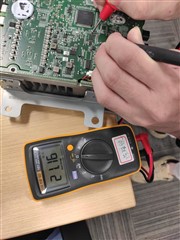
12V battery is connected to VBAT_IN -> pull SHDNZ up -> register initialization -> enable ADC and output TDM to Audio DSP -> pull SHDNZ low to high -> register initialization -> enable ADC and output TDM to Audio DSP

Phenomenon: 

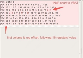
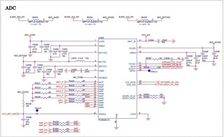
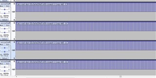
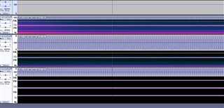
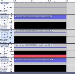
Recording data is abnormal. It has reproduced 5 times. You can find the waveform and schematic as below. 

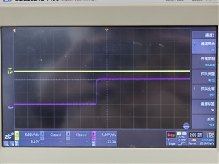
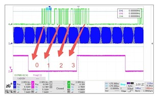
Waveform: (CH1: BCLK CH2: LRCK CH4: DATA)


Schematic: 

Data: 

Phenomenon 1: DC signal captured when abnormal(reproduced twice)

Phenomenon 2: looks like some specific frequency point noise(reproduced once)

Phenomenon 3: noise(reproduced once)

Thanks!

Ethan Wen

  • Hi Ethan,

    Are you using the same register configuration both times? I assume the recording works correctly when the device is first initialized?

    Refer to the paragraph below from the data sheet and ensure that the customer is holding SHDZ low for the proper amount of time: 

    If the SHDNZ pin is asserted low when the device is in active mode, the device ramps down volume on the record data, powers down the analog and digital blocks, and puts the device into hardware shutdown mode in 25 ms (typical). The device can also be immediately put into hardware shutdown mode from active mode if the SHDNZ_CFG[1:0], P0_R5_D[3:2], register bits are set to 2'b00. After the SHDNZ pin is asserted low, and after the device enters hardware shutdown mode, keep the SHDNZ pin low for at least 1 ms before releasing SHDNZ for further device operation.

    Best regards,
    Jeff McPherson

  • Hi Jeff, 

    Clarify the test procedure. 

    Test procedure: 

    12V battery is always connected to VBAT_IN

    PCM6260 power on->pull SHDNZ up -> register initialization -> enable ADC and output TDM to Audio DSP -> recording -> pull SHDNZ down-> PCM6260 power off

    Are you using the same register configuration both times? I assume the recording works correctly when the device is first initialized?

    Yes. Every test starts from poweroff, the sequence and register configuration are identical.

    Recording stop workding at the beginning.

    Refer to the paragraph below from the data sheet and ensure that the customer is holding SHDZ low for the proper amount of time: 

    SHDN is assert for ~2 seconds after PCM6260 power ramps up.

    Thanks!

    Ethan Wen

  • Hi Ethan,

    Can you provide me the full register initialization script?

    Thanks,
    Jeff McPherson

  • Hi Jeff, 

    See below the register initialization. Please help take a look and provide some suggestions to help debug. This project will go to production soon and we have much pressure from customer side. 


    1. SHDN=LOW
    2. board power on
    3. board init takes 200~300ms
    4. SHDN=HIGH
    5. ADSP init takes 1.6s
    6. load PCM6260 register configurations


        pcm6260_action(SLEEP_CFG, 0x05);

        msleep(2);


        pcm6260_action(SHDN_CFG, 0x05);


        pcm6260_action(ASI_CFG0, 0x74);


        pcm6260_action(ASI_CFG1, 0x00);

        pcm6260_action(ASI_CFG2, 0x00);


        pcm6260_action(ASI_CH1, 0x00);

        pcm6260_action(ASI_CH2, 0x01);

        pcm6260_action(ASI_CH3, 0x02);

        pcm6260_action(ASI_CH4, 0x03);

        pcm6260_action(ASI_CH5, 0x20);

        pcm6260_action(ASI_CH6, 0x21);


        pcm6260_action(MST_CFG0, 0x02);

        pcm6260_action(MST_CFG1, 0x48);

        pcm6260_action(ASI_STS, 0xFF);

        pcm6260_action(CLK_SRC, 0x10);


        pcm6260_action(BIAS_CFG, 0xd0);

        pcm6260_action(CH1_CFG0, 0x38);

        pcm6260_action(CH1_CFG1, 0x24);

        pcm6260_action(CH1_CFG2, 0xD7);

        pcm6260_action(CH1_CFG3, 0X80);

        pcm6260_action(CH1_CFG4, 0x00);

        pcm6260_action(CH2_CFG0, 0x38);

        pcm6260_action(CH2_CFG1, 0x24);

        pcm6260_action(CH2_CFG2, 0xD7);

        pcm6260_action(CH2_CFG3, 0X80);

        pcm6260_action(CH2_CFG4, 0x00);

        pcm6260_action(CH3_CFG0, 0x38);

        pcm6260_action(CH3_CFG1, 0x24);

        pcm6260_action(CH3_CFG2, 0xD7);

        pcm6260_action(CH3_CFG3, 0x80);

        pcm6260_action(CH3_CFG4, 0x00);

        pcm6260_action(CH4_CFG0, 0x38);

        pcm6260_action(CH4_CFG1, 0x24);

        pcm6260_action(CH4_CFG2, 0xD7);

        pcm6260_action(CH4_CFG3, 0X80);

        pcm6260_action(CH4_CFG4, 0x00);

        pcm6260_action(CH5_CFG0, 0x10);

        pcm6260_action(CH5_CFG1, 0x00);

        pcm6260_action(CH5_CFG2, 0xC9);

        pcm6260_action(CH5_CFG3, 0X80);

        pcm6260_action(CH5_CFG4, 0x00);

        pcm6260_action(CH6_CFG0, 0x30);

        pcm6260_action(CH6_CFG1, 0x00);

        pcm6260_action(CH6_CFG2, 0xC9);

        pcm6260_action(CH6_CFG3, 0X80);

        pcm6260_action(CH6_CFG4, 0x00);


        pcm6260_action(DIAG_CFG1, 0x37);

        pcm6260_action(DIAG_CFG2, 0x8f);

        pcm6260_action(DIAG_CFG3, 0xb8);

        pcm6260_action(DIAG_CFG4, 0x00);


        pcm6260_action(DSP_CFG0, 0x01);

        pcm6260_action(DSP_CFG1, 0x24);


        pcm6260_action(AGC_CFG0, 0xe7);


        pcm6260_action(IN_CH_EN, 0xf8);

        pcm6260_action(ASI_OUT_CH_EN, 0xf8);

        pcm6260_action(PWR_CFG, 0xe8);


        msleep(15);


        pcm6260_action(DIAG_CFG0, 0xf0);

    Thanks!

    Ethan Wen

  • 12V battery is always connected to VBAT_IN

    PCM6260 power on->pull SHDNZ up -> register initialization -> enable ADC and output TDM to Audio DSP -> recording -> pull SHDNZ down-> PCM6260 power off

    Hi Ethan,

    Sorry I didn't notice the test procedure changed. So the device is being fully powered down? And the recording works the first time but fails on subsequent starts? How do you return the device to the working state?

    I copied the customer configuration into my EVM and the recording is reliable through multiple resets and power ups. So I need some more detail on how exactly the phenomenon is being reproduced.

    Thanks,
    Jeff McPherson

  • Hi Jeff,

    Thank you for your support. I am the guy raised this question.

    Sorry I didn't notice the test procedure changed. So the device is being fully powered down? And the recording works the first time but fails on subsequent starts? How do you return the device to the working state?

    In terms of PCM6260, the sequence of a fully test cycle is:

    • SHDN=LOW
    • board power on
    • board init takes 200~300ms
    • SHDN=HIGH
    • ADSP init takes 1.6s
    • load PCM6260 register configurations
    • recording
    • SHDN=LOW
    • board power down for ~20s

    The recording works every test until it fails and it fails from the beginning of test. It take hours or days to reproduces.

    Re-powering and initing PCM6260 will take it back to working state.

    However I get 2 different results:

    1. when problem occurs, reading PCM6260 registers is ok, and recording returns to working state after reiniting PCM6260 registers

    2. when problem occurs, reading PCM6260 registers leads to occasional  I2C IO error, but all registers' values are 0x00

    and reiniting PCM6260 registers doesn't take it to working state.

    Best Regards

    Lihua

  • Hi Jeff, 

    Please help suggest some next steps for both data recording issue and new issue here. Customer is pushed by their OEM and they will have meeting with OEM next Monday. 

    Except this data recording abnormal issue, customer found the short to Vbat1 fault false trigger issue in one of the DUT. We just found one DUT with this issue. You can find the details as below. 

    Phenomenon: 

    After powering up PCM6260-Q1 and enable the input DC fault diagnostic on IN1 to IN4, PCM6260-Q1 reported IN1 to IN4 short to VBAT_IN fault in latch status register. You can find the register dump as below. 

    CH1_LTCH/CH2_LTCH/CH3_LTCH/CH4_LTCH=0x02

    INT_LTCH1=0xf0

    INT_LTCH3=0xa0


    We also used multimeter to measure the IN1P~IN4P impedance. The result is Mohm level. 

    We also captured the waveform on INx and VBAT_IN after powering up. Based on the short to Vbat mechanism, we don't see the actual fault. 

    CN1=IN1P, CH4=VBAT

    Customer also checked the register value which they written in, it seems I2C communication is OK. 

    Any suggestions on this? 

    Thanks!

    Ethan Wen

  • After powering up PCM6260-Q1 and enable the input DC fault diagnostic on IN1 to IN4, PCM6260-Q1 reported IN1 to IN4 short to VBAT_IN fault in latch status register. You can find the register dump as below. 

    Hi Jeff, 

    Please ignore the noise  " SHDNZ 0" in the picture. SHDNZ is pulled to high level actually.

    Regards

    lihua

  • Hi Ethan and Lihua,

    Unfortunately our expert on the diagnostics doesn't return until Monday. I am not as experienced with this feature. I recommend trying to clear the latched diagnostics registers to see if the VBAT fault clears or remains. Also try adjusting the threshold to see if anything changes.

    Since this is a one off failure and if my recommendations don't work, you can try to report it as a faulty device and return it so we can take a look at it.

    As for the faulty recording, I would try to measure the power supplies during the test sequence. The power supplies must be stable before SHDNZ is released. You might need to extend the board power up window to guarantee that the supplies are stable, there is no ringing, etc. I am confident this is an issue with the supplies/power sequence and not any register settings.

    Best regards,
    Jeff McPherson

  • Hi Jeff,

    Thank you for advices.

    I recommend trying to clear the latched diagnostics registers to see if the VBAT fault clears or remains. Also try adjusting the threshold to see if anything changes.

    the latched status should self clear on read, and the threshold is the highest one, but  i will give it a try.

    one thing we did hours ago , we disable diagnosis but the device is still faulty.

    As for the faulty recording, I would try to measure the power supplies during the test sequence. The power supplies must be stable before SHDNZ is released. You might need to extend the board power up window to guarantee that the supplies are stable, there is no ringing, etc. I am confident this is an issue with the supplies/power sequence and not any register settings.

    we measured the timing and supply before but didn't find anything wrong. we will check it again and extend the windows to 1.5s. 

    Regards,

    lihua 

  • Hi Jeff,

    Unfortunately our custom found more non-working devices.

    Device 1

    IN2~4 are ok. IN1P impedence is 3KΩ. Replacing with a good part will take the device back to working i.e MIC recording works now.

    This chip had been returned to TI for FA.

    Device 2

    I recommend trying to clear the latched diagnostics registers to see if the VBAT fault clears or remains. Also try adjusting the threshold to see if anything changes.

    the latched status should self clear on read, and the threshold is the highest one, but  i will give it a try.

    one thing we did hours ago , we disable diagnosis but the device is still faulty.

    The AVDD impedence is ~300Ω and the chip is realy hot. The analog part might stop working so we get wrong diag result.

    Replacing with a good part will take the device back to working i.e MIC recording works now.

    This chip had been returned to TI for FA too.

    Device 3/4

    IN1~4 are not working, and  MBIAS is 2.8V (should be 8V). Reading diag register shows there is a MBIAS overcurrent error.

    Device 5

    IN2~4 are ok. IN1P recording is not working. We have not received this device for further test yet.

    As for the faulty recording, I would try to measure the power supplies during the test sequence. The power supplies must be stable before SHDNZ is released. You might need to extend the board power up window to guarantee that the supplies are stable, there is no ringing, etc. I am confident this is an issue with the supplies/power sequence and not any register settings.

    we measured the timing and supply before but didn't find anything wrong. we will check it again and extend the windows to 1.5s. 

    We measure the timing and voltage again, PCM6260 supplies are stable before releasing SHDNZ.

    However this device is broken now and the IOVDD impedence is wrong. I don't know what happens. I will get a new board to test.

    Best Regards

    Lihua

  • Hi Jeff, 

    Since there have reported more and more failure cases, we plan to review all the procedures to check the potential root cause. 

    May you kindly help review their schematic to check if any potential risks? 

    Please also let me know if have any ideas to locate the root cause. 

    Thanks!

    Ethan Wen 

  • Hi Ethan,

    Could you share the part of the schematic that includes the mic signals? Otherwise the schematic that was shared at the beginning seems fine. I would bring attention that AVDD has an absolute maximum of 3.9V. Based on the descriptions given before, I suspect either AVDD is being damaged or the input pins are being damaged or both.

    Best regards,
    Jeff McPherson

  • Hi Jeff, Ethan;

    Below is the first and second dump of device 3 and 4.

    IN1~4 are not working, and  MBIAS is 2.8V (should be 8V). Reading diag register shows there is a MBIAS overcurrent error.
    #3
    [05/08/2024 11:05:00.055] 204842.0:{audio}[4]MIC 0 0 0 5 0 0 5 0 74 0 0 0 0 1 2 3 20
    [05/08/2024 11:05:00.072] 204847.0:{audio}[4]MIC 10 21 6 7 2 48 48 10 10 4 20 2 8 0 0 2 40
    [05/08/2024 11:05:00.088] 204851.0:{audio}[4]MIC 20 0 22 0 0 0 0 0 0 0 ff 3 0 d8 f0 8 0
    [05/08/2024 11:05:00.088] 204855.0:{audio}[4]MIC 30 0 0 0 0 0 d0 0 0 ba 4b 10 d0 38 24 d7 80
    [05/08/2024 11:05:00.088] 204860.0:{audio}[4]MIC 40 0 38 24 d7 80 0 38 24 d7 80 0 38 24 d7 80 0
    [05/08/2024 11:05:00.107] 204865.0:{audio}[4]MIC 50 10 0 c9 80 0 30 0 c9 80 0 0 0 c9 80 0 0
    [05/08/2024 11:05:00.107] 204869.0:{audio}[4]MIC 60 0 c9 80 0 f0 37 8f b8 0 0 0 1 24 7b 0 0
    [05/08/2024 11:05:00.107] 204873.0:{audio}[4]MIC 70 e7 0 0 f8 f8 e8 f8 f8 0 0 ff 0 ff 90 8d 0
    [05/08/2024 11:28:16.503] 11302.0:{audio}[4]MIC 0 0 0 5 0 0 5 0 74 0 0 0 0 1 2 3 20
    [05/08/2024 11:28:16.504] 11306.0:{audio}[4]MIC 10 21 6 7 2 48 48 10 10 4 20 2 8 0 0 2 40
    [05/08/2024 11:28:16.507] 11310.0:{audio}[4]MIC 20 0 22 0 0 0 0 0 0 0 ff 3 0 d8 f0 8 0
    [05/08/2024 11:28:16.522] 11314.0:{audio}[4]MIC 30 8 0 0 0 0 0 0 0 ba 4b 10 d0 38 24 d7 80
    [05/08/2024 11:28:16.524] 11320.0:{audio}[4]MIC 40 0 38 24 d7 80 0 38 24 d7 80 0 38 24 d7 80 0
    [05/08/2024 11:28:16.524] 11325.0:{audio}[4]MIC 50 10 0 c9 80 0 30 0 c9 80 0 0 0 c9 80 0 0
    [05/08/2024 11:28:16.538] 11329.0:{audio}[4]MIC 60 0 c9 80 0 f0 37 8f b8 0 0 0 1 24 7b 0 0
    [05/08/2024 11:28:16.542] 11333.0:{audio}[4]MIC 70 e7 0 0 f8 f8 e8 f8 f8 0 0 ff 0 ff 90 8d 0
    #4
    [05/08/2024 11:33:53.303] 135731.0:{audio}[4]MIC 0 0 0 5 0 0 5 0 74 0 0 0 0 1 2 3 20
    [05/08/2024 11:33:53.303] 135735.0:{audio}[4]MIC 10 21 6 7 2 48 48 10 10 4 20 2 8 0 0 2 40
    [05/08/2024 11:33:53.320] 135741.0:{audio}[4]MIC 20 0 22 0 0 0 0 0 0 0 ff 3 0 d8 70 0 8
    [05/08/2024 11:33:53.320] 135745.0:{audio}[4]MIC 30 8 8 0 0 0 0 0 40 ba 4b 10 d0 38 24 d7 80
    [05/08/2024 11:33:53.320] 135749.0:{audio}[4]MIC 40 0 38 24 d7 80 0 38 24 d7 80 0 38 24 d7 80 0
    [05/08/2024 11:33:53.320] 135753.0:{audio}[4]MIC 50 10 0 c9 80 0 30 0 c9 80 0 0 0 c9 80 0 0
    [05/08/2024 11:33:53.320] 135759.0:{audio}[4]MIC 60 0 c9 80 0 f0 37 8f b8 0 0 0 1 24 7b 0 0
    [05/08/2024 11:33:53.320] 135763.0:{audio}[4]MIC 70 e7 0 0 f8 f8 e8 f8 f8 0 0 ff 0 ff 90 8d 0
    [05/08/2024 11:36:08.441] 270915.0:{audio}[4]MIC 0 0 0 5 0 0 5 0 74 0 0 0 0 1 2 3 20
    [05/08/2024 11:36:08.441] 270921.0:{audio}[4]MIC 10 21 6 7 2 48 48 10 10 4 20 2 8 0 0 2 40
    [05/08/2024 11:36:08.444] 270925.0:{audio}[4]MIC 20 0 22 0 0 0 0 0 0 0 ff 3 0 58 f0 8 8
    [05/08/2024 11:36:08.448] 270929.0:{audio}[4]MIC 30 8 8 0 0 0 0 0 40 ba 4b 10 d0 38 24 d7 80
    [05/08/2024 11:36:08.483] 270933.0:{audio}[4]MIC 40 0 38 24 d7 80 0 38 24 d7 80 0 38 24 d7 80 0
    [05/08/2024 11:36:08.483] 270939.0:{audio}[4]MIC 50 10 0 c9 80 0 30 0 c9 80 0 0 0 c9 80 0 0
    [05/08/2024 11:36:08.483] 270943.0:{audio}[4]MIC 60 0 c9 80 0 f0 37 8f b8 0 0 0 1 24 7b 0 0
    [05/08/2024 11:36:08.483] 270948.0:{audio}[4]MIC 70 e7 0 0 f8 f8 e8 f8 f8 0 0 ff 0 ff 90 8d 0
    Best Regards
    Lihua
  • The AVDD impedence is ~300Ω and the chip is realy hot. The analog part might stop working so we get wrong diag result.

    The AVDD impedence is 49Ω.

  • Hi Lihua,

    Thank you for the info. Closing this thread as we have moved the discussion to email.

    Best regards,
    Jeff McPherson