This thread has been locked.
If you have a related question, please click the "Ask a related question" button in the top right corner. The newly created question will be automatically linked to this question.
Tool/software:
Dear Experts,
I'm working on a project, using TLV320AIC3120IRHBT.
In my design, I use the microphone: CMM-2718AT-38164W-TR and speaker 8 ohms: CDS-13138-SMT-TR.
I'm in bringing-up phase, I want to confirm the hardware with microphone and speaker are fine firstly.
My plan: Using bypass analog path: MIC1LP -> Class D Driver directly (without PGA, ADC, DAC). But I didn't hear any thing from speaker when I made the sound into microphone.
I have some questions
1, This way is proper to test microphone? Because when I touch my hand into microphone line, I can see the change at output from speaker. I thought the bypass loop works so I was worried that microphone didn't work.
Should I configure the Rin for MIC1LP?
2, Which is different between my way to test bypass analog and using loop ADC-DAC?
3, I'm confused with total gain of Class D driver + analog attenuation before this driver. It seems that having the constrain for these value? because I tried configure gain = 24dB and attenuation is 0db, the D0 of 0x2A - page 1 is 0, that means the gain is not applied.
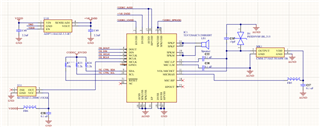
Below is the schematic.
Thank and best regards,
Hi Dao,
1) Personally, I prefer to test just the ADC path first by recording to your I2S host. Then test playback by playing from the I2S host to the class-D. I do it this way because it reduces the amount of unknowns. However your testing is still valid. You can try to adjust the Rin for MIC1LP but I'm not confident it will create much change.
2) The only difference between your way and the ADC-DAC loopback is that the gain stages will be different. Also the quality will be different since there will be conversions between analog and digital domains.
3) Are you applying I2S/MCLK clocks when you program the gain/attenuation? Because of the soft-stepping feature, the gain change requires clocking. Have you double checked that all power supplies are stable and at expected values?
Best regards,
Jeff McPherson
Hi Jeff,
Thanks for your reply.
1, Firstly, I thought loop only analog path is simple way to confirm the hardware side and this is urgent with us right now.
2, About quality, do you think using ADC-DAC loop is better than analog path loop?
3, All power sources are good. I think I should check I2S/MCLK as you recommend.
Regards,
Hi Dao,
I don't believe testing analog vs digital loop is "better" than the other. My recommendation is just to test how you are going to use the codec, but it can help to break the loop down into smaller parts and test from there.
Let me know the result of checking the clocks.
Thanks,
Jeff McPherson
void tlv320_clock_cfg(struct baudio_inst *inst) { // ---------------------------------------------------------------------------- // Clock configurations : Copy from the excel // ---------------------------------------------------------------------------- // Selecting page 0 tlv320_write_byte_check(inst, 0x00, 0x00); // Reset tlv320_write_byte(inst, 0x01, 0x01); tlv320_write_byte_check(inst, 0x00, 0x00); tlv320_write_byte_check(inst, 4, 0x00); tlv320_write_byte_check(inst, 5, 0x91); tlv320_write_byte_check(inst, 6, 0x01); tlv320_write_byte_check(inst, 11, 0x81); tlv320_write_byte_check(inst, 12, 0x84); tlv320_write_byte_check(inst, 13, 0x00); tlv320_write_byte_check(inst, 14, 0x40); tlv320_write_byte_check(inst, 18, 0x81); tlv320_write_byte_check(inst, 19, 0x84); tlv320_write_byte_check(inst, 20, 0x40); vTaskDelay(20); tlv320_write_byte_check(inst, 0x00, 0x00); tlv320_write_byte_check(inst, 27, 0x0D); tlv320_write_byte_check(inst, 28, 0x00); tlv320_write_byte_check(inst, 29, 0x24); //DIN to DOUT loopback enable tlv320_write_byte_check(inst, 30, 0x84); tlv320_write_byte_check(inst, 33, 0x00); vTaskDelay(20); tlv320_write_byte_check(inst, 0x00, 0x00);//Select page 0 tlv320_write_byte_check(inst, 63, 0xB5); //DAC is power-up, DAC path = left+right, tlv320_write_byte_check(inst, 64, 0x04); //DAC is not muted tlv320_write_byte_check(inst, 65, 0x30); // DAC digital gain = 24dB vTaskDelay(20); tlv320_write_byte_check(inst, 0x00, 0x01); tlv320_write_byte_check(inst, 35, 0x40); //DAC is routed to the mixer amplifier vTaskDelay(20); tlv320_write_byte_check(inst, 0x00, 0x01); tlv320_write_byte_check(inst, 36, 0x00); tlv320_write_byte_check(inst, 38, 0x81); // Analog Voulum control for speaker -0.5dB vTaskDelay(20); tlv320_write_byte_check(inst, 0x00, 0x01); tlv320_write_byte_check(inst, 32, 0x86); //Class D-Driver is powered up tlv320_write_byte_check(inst, 42, 0x05); //Class D-Driver gain = 6dB vTaskDelay(20); tlv320_write_byte_check(inst, 0x00, 0x00); tlv320_write_byte_check(inst, 81, 0x81); tlv320_write_byte_check(inst, 82, 0x00); tlv320_write_byte_check(inst, 83, 0x00); tlv320_write_byte_check(inst, 0x00, 0x01); tlv320_write_byte_check(inst, 46, 0x0B); tlv320_write_byte_check(inst, 48, 0x40); tlv320_write_byte_check(inst, 49, 0x10); }
Hi Jeff,
I'm so sorry about delay response.
I added the code for register configuration below. Please check it and give me some help.
This code for DIN-DOUT loop back.
Again, With Attenuation -0.5dB and Class-D gain = 6dB, bit 0 of R42/page 1 returns 0, that means gains to class D has not applied.
Hi Dao,
I see your soft stepping is enabled in your code. Are I2S clocks being applied to the codec? Soft stepping requires that I2S clocks be running, otherwise the gain will not change values.
Best regards,
Jeff McPherson
Hi Jeff, Thanks for your reply.
Btw, I want to ask about waveform for SPKP and SPKM.
I probed these line (between them), The waveform is as below image.
My coding is for loop analog path (MIC to SPK).
Why the wave form is square? and why its frequency is around 660KHz?
Hi Dao,
The SPK+ and - outputs are Class-D. Class-D outputs are PWM type signals that must be demodulated in order to return the original signal. Measuring directly with a scope, you will see the switching signal instead of the smooth analog signal from the mic. You should use a low pass filter (fc =~20kHz) before measuring the output. The data sheet specs are measured with this low pass filter in place.
The 660kHz is related to the switching frequency of the signal i.e. the modulation carrier frequency.
Best regards,
Jeff McPherson
Hi Jeff,
Right now, when I configure the loop analog path, I using sweep from 20Hz to 20,000Hz, I just hear the sound from 1.6Khz to 8KHz.
Could you have some advice for me about this issue?
the p/n of speaker: CDS-13138-SMT-TR
Regards,
Dao,
Your speaker data sheet shows that it does not support the full 20Hz to 20kHz range. That's why you're not hearing the full sweep.
Best regards,
Jeff McPherson
the lower limit is 1.6KHz, I can see. but with upper limit is 8KHz, I don't understand. Could you help me about this?
Hi Dao,
What is the sample rate you are running the codec at. Are you running into a nyquist limit? I would also recommend observing with a low pass filter and probe what is happening electrically to confirm if it is a speaker issue or not.
Best regards,
Jeff McPherson
Hi Jeff,
I found the issue with sensitivity of my microphone.
Thanks alot about your support.