This thread has been locked.

If you have a related question, please click the "Ask a related question" button in the top right corner. The newly created question will be automatically linked to this question.

Powering TLE2072 with a single supply.

Other Parts Discussed in Thread: TLE2072, OPA2322, TINA-TI

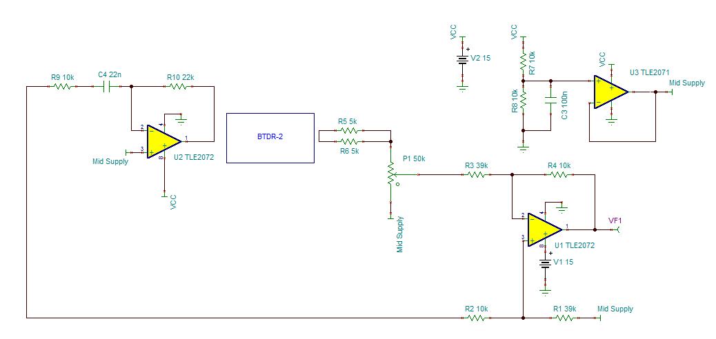
Hello! I'm new to the world of op amps and I'm a little confused on how to power them properly. I'm planning on using the TLE2072 as an audio buffer for a reverb circuit. One half will be used as an input buffer before the digital reverb chip and the other half will be used as an output buffer. I have seen in other circuits that if I use a voltage divider on the signal input, it should work properly. My question is, if the signal input is different on the second half of the op amp (i.e.. after it has been processed by the digital reverb), will I still need to create a voltage divider network on the slightly different signal?

Here's a link to the circuit I'm planning on building

  • Hi, Jason,

    Welcome to e2e, and thanks for your interest in our products!

    I have asked my colleague in the op amp group to address your concerns on the TLE2072.

    -d2

  • Jason,

    When determining the power supply requirements for an op amp, it is best to first determine what the signal ranges are on the input and the output of the op amp. Op Amps cannot accurately amplify signals that have voltages outside of their power supplies. In fact, real op amps have trouble amplifying signals that are even close to their power supply voltages. The input range of an op amp is normally specified in the datasheet with the label "common-mode input voltage". Below is the spec from the TLE2072 datasheet:

    Here it is specified for two different power supply conditions, but in both cases notice that the input voltage cannot be within 4.1V of the negative power supply! Looking at the schematic that you link to, I am assuming that you had planned to power the TLE2072 on a single 5V supply? This will limit the range of input signals for which the TLE2072 will function properly to 4.1 - 5 V. This is most likely unacceptable in your design. If you are constrained to a 5V single supply, my suggestion is to use an op amp which was specifically designed to operate on a single supply. Low voltage op amps typically incorporate a "rail-to-rail" input (and/or output) stage which allows much closer operation to the power supply rails. The OPA2322 is one part which is designed to operate on a 5V supply and would work for your application. Here I show using a voltage divider on the non-inverting input to apply a 2.5V DC bias to the inputs. Now the input and output voltages are centered around 2.5V which allows for proper operation of the op amp. 

    I highly suggest you download TI's free analog circuit simulator Tina-TI and use it to test the op amp circuits in your design before you build it. This can really help you save time and money in a project. 

  • I'm planning on powering the TLE2072 with a 15v power supply. The only thing being powered by 5v will be the actual reverb circuit via the voltage regulator. The other limitation is the fact that I don't really have the ability to solder much smaller surface mount components such as the SOIC package used with the OPA2322. The much bigger PDIP package that the TLE2072 comes in is easier for me to work with since I can just use sockets mounted to the board.

  • Jason,

    With a 15V power supply, you can bias the TLE2072s to their mid supply point. Reading the website of the BTDR-2 it appears that this component has AC coupled inputs and outputs so it should not be affected by the additional DC. However, the website does not state what the maximum DC voltage is that can appear at the input or output of the BTDR-2 so it would be good to ask that company what the part's limitations are. With this in mind, your circuit can be reconfigured as follows:

    Op Amp U3 creates a low impedance mid-supply voltage that is applied to all of the points marked "common" in your diagram. This allows the circuit to function within the input voltage limitations of the TLE2072. It's important to remember that your output will have a 7.5V DC voltage as well as the output waveform so it would be a good idea to add a capacitor to the output to prevent damaging anything that is connected to this circuit. 

  • Awesome! Thanks so much!

    How do you know where to apply a mid supply in circuits like these? I have another one that I'm also working on that I'm a little stuck on. How would I apply that same concept to this circuit? http://www.gtechblues.com/images/DI_Box_1.jpg

    Also, you mentioned that I should add a capacitor to the output. How would I determine what value I should use and how would I go about connecting it?