This thread has been locked.

If you have a related question, please click the "Ask a related question" button in the top right corner. The newly created question will be automatically linked to this question.

TAS5708 failing

Other Parts Discussed in Thread: TAS5708

Hi,

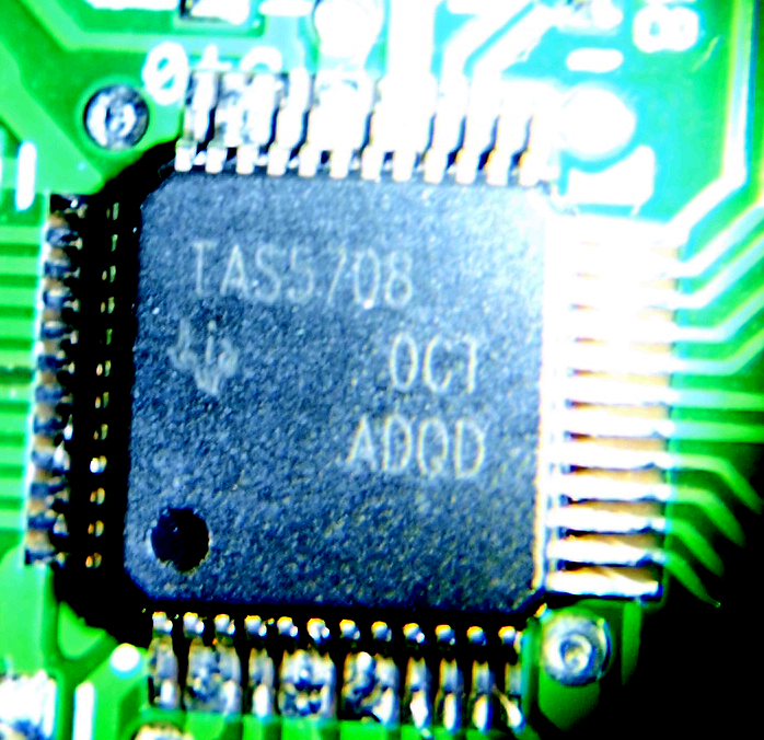
Recently, we designed an Audio amplifier based on TAS5708. They all work great when they work!

However, sometime they just die. Sometimes they die during power up, sometimes when they are play music, and sometime when just sitting there with NO SIGNAL!

This has happened with all supply voltages 12V, 20V, 24V. Sometimes they die in 5 minutes, and sometime in 30 minutes. The ones that get passed 1 hour tend to live.

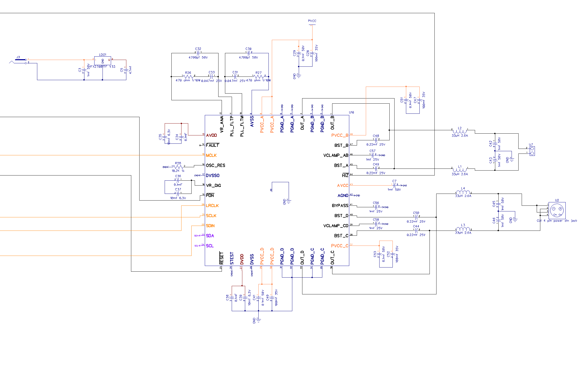
In short, I have not been able to narrow down the cause of this failure. BUT the one thing they all have in common is that when this happens, the impedance of the HIZ pin drops from about 90KOhm to around 0.88 kOhm

I'm also suspicious about the authenticity of the chips because they were not assembled by us, and they can be found for cheap on Alibaba. So I'm afraid the company that made the boards for us, might have used chips from unauthorized sellers (contrary to what they tell us). They are a North America company with factories in China.

If any of the above rings a bell or if you have any comments, please let me know. These failures are pretty embarrassing for our company.

I can supply more info (i.e. schematic, layout ) on demand.

Regards,

  • Hi Siavash,

    Can you please provide the lot-trace code (inscribed on top of the package) of these devices? 

    What is the speaker impedance & output power level being used? Please provide the schematic files for review.

    -Ravi

  • Hi Ravi,

    Thanks for the prompt response.

    This is what I see on the chips:

    TAS5708

    OCT

    ADQD

    Each channel is driving a small 8Ohm fullrange driver rated at 15W. In the past we have used TA2024 chips with the same driver with no issues.

    Also the prototype (more than 8 month old) that we made with the chip bought from digikey, works fine even though it was subject to a lot of testing and abuse 

    Above is the TAS5708 part of the schematic. All the capacitors are placed as closely as possible to the chip on a four layer board.

    Let me know if you need more info.

    Thanks again,

  • Also here is some more info that might help determining the authenticity of the chips:

    1. They tell me they got the chips from Digikey

    2. They bought them around November of 2012

  • Hi Siavash,

    Thanks for the info. I checked the lot-trace code you provided & it seems to be a valid one. 

    I also checked the shipping trend and as expected the TAS5708 has shipped in large volumes over the last several years and has a phenomenally low DPPM rate. 

    Couple of follow-up questions regarding the failures & schematic......

    1.) Does I2C read-write work on these devices? What is the readback from the error-register?

    2.) What is the DC-level on BST & GVDD pins?

    3.) On the schematic does mF refer to micro-Farad?? (I think it does, but just wanted to confirm) e.g. BST cap says 0.22mF.

    4.) On the schematic, what is U2 ? (connected to channels C&D)?

    -Ravi

  • Hi Ravi,

    1.) Does I2C read-write work on these devices? What is the readback from the error-register?

    Yes, I2C read-write works, and the error register returns no errors.

    2.) What is the DC-level on BST & GVDD pins?

    I'm not sure which pin is GVDD? but here are some voltage measurements:

    PVCC_A = PVCC_B = PVCC_C = PVCC_D = AVCC = 19.9

    AVDD = DVDD = 3.2

    BST_C = BST_D =11.5

    VCLAMP_CD = 12.1

    BST_A  = BST_B =11.4

    VCLAMP_AB = 11.9

    BYPASS = 0

    HIZ = 0

    Fault = 3.2

    3.) On the schematic does mF refer to micro-Farad?? (I think it does, but just wanted to confirm) e.g. BST cap says 0.22mF.

    Yes mF refers to micro-Farad

    4.) On the schematic, what is U2 ? (connected to channels C&D)?

    That is just an output jack.

    Also, There is no PWM signal present on the outputs, and outputs are at 0V before initialization and jump to about 70mV after initialization 

    Please, let me know if you need more info. Regards,

  • Siavash,

    Here are a few notes/issues related to the schematic you posted.

    1.) Pin-43 (AVCC) only has a 1uF to GND.  -- This pin should instead be connected to PVCC.

    2.) Cap's on pin-13 (AVDD) , pin-18 (VR_DIG) , pin-37 (PVCC-C) are not connected to ground.

    -Ravi

  • Hi Ravi,

    These issues have actually to do with our schematic software. Nets are color coded.

    All the ORANGE nets (except MCLK, LRCLK, SCLK, SDIN) are connected to PVCC

    All BLUE nets are connected to GND

    All RED nets are connected to 3.3V

    For example, the caps on the PVCC-C are orange on one end, and blue on the other end. That means they are connected between PVCC and GND

  • Siavash,

    Thanks for clarifying. The schematic seems to check out fine. 

    Have you tried using some samples from the batch on the evaluation board and run similar check-out tests? 

    -Ravi

  • Hi Ravi,

    Thanks for reviewing the schematics. The company who made the boards also supplied all the parts. So I don't have any left over parts from the batch.

    Does the fact that the resistance of the HIZ pin drops from 90K to 0.8K on dead chips mean anything to you? I think this is good clue for finding out what goes wrong inside the chip.

    Thanks,

  • Hi Ravi,

    Any thoughts on the HIZ pin?

    Thanks,