This thread has been locked.

If you have a related question, please click the "Ask a related question" button in the top right corner. The newly created question will be automatically linked to this question.

TAS5630/13 major clipping problem

Other Parts Discussed in Thread: TAS5613, TAS5630, TAS5630B

Hello,

I would like to ask help of you people, since I cannot figure it out. Problem is, that when amplifier is about to enter clipping, it rings badly. To my concern, its not fault of board layout, because we made three different prototypes, and they did exactly the same thing, other than that, circuit works on 100%. Circuit is almost the same as TI´s eval board, I´ve already burned thing in, at 300W RMS for 8 hours, an no problems, it withstood numerous shor at output, and over temperature also works, its really good amp, but this problem ruins it. When Linear AB class people see this, they automatically start with blabbering how bad the D class is.. so anyway, here are the pictures what it looks like.

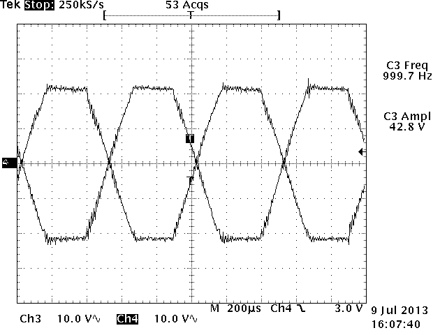
Normal operation, just bellow clip, we already see some blurring on the top of sine:

Start of clipping, THIS IS THE PROBLEM:

Hard clipping:

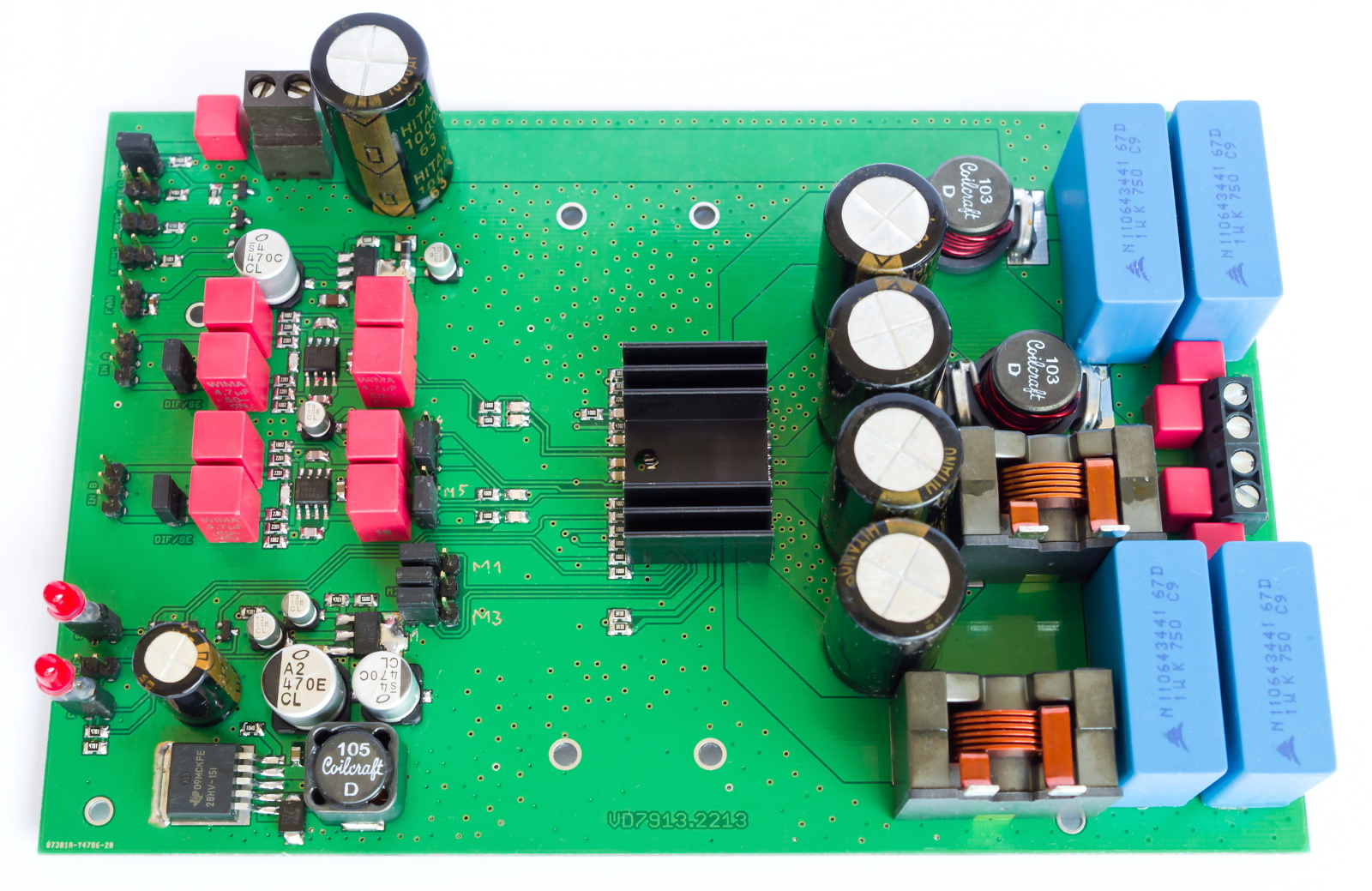
And this is how the thing looks like: http://adresat.rajce.idnes.cz/TAS5613#IMGP7297.jpg  >you can browse in album for more pics.

Any help is apreciated, thank you.

  • Hello Branislav,


    Welcome to E2E!

    I have a few questions regarding the design -

    1. AD or BD mode of operation?

    2. AD or BD mode LC filter used? Does the ringing reduce with BD mode filter? BD mode filter can be used for both AD and BD mode of operation.

    3. Inductor current rating?

    4. Do you see ringing when you do a differential measurement (OUTP-OUTN) on the scope?


    reg,

    Paul Chen

    Applications Engineer

    Dallas TX USA

  • Well hello!

    Circuitry around IC is same as EVAL, so according to setting of MODE pins, and C/D inputs its BD modulation.

    1. BD mode.

    2. Same as in eval, so BD type, 12uH+1uF on each side of bridge.

    3. Inductors are CoilCraft DO5040H-123MLB, so 12uH with Irms=7.4A, and Isat=15.9A.

    4. I see it either referenced to ground, and some less in amplitude in differential, maybe it cancels out a bit.

    Thanks in advance.

    I found scope screenshots from previous prototype, it digital, so you can see nature of that ringing:

  • I wonder if the inductors are saturating (they do have a pretty steep sat curve). What is the output current, the Rocp resistor value, PVDD voltage, resistive load used (impedance), TAS5630 or TAS5613 used?

    reg,

    Paul.


  • This board is with 5613 (digi scope pictures are from 5630, so its same), OC_ADJ resistor is 22k, Voltage is maximum PVDD=35V, load is purely resistive (well as much as possible, SMD chip resistors, plenty of them) and value is 4 or 8 Ohms, but it rings on both loads, current is in the case of ringing just starting, about 4.7A for 4Ohm load.

  • Hi, about  1 year ago I did a lot of measurements and experiments with TAS5630 from which the digital scopes is shown above. I used TAS5630 in DKD package on PCB mentioned by Branislav. I powered the board from heavy filtered 35VDC, later I went up to 46VDC. I loaded the output by low-induction 3R9 load composed of 100 SMD resistors :) The problem was, that nasty ringing was appeared even far _before_ clipping. It's demonstrated on this video http://rayer.g6.cz/1tmp/tas5630/test%20limitace-Vdd=35V,%20Rz=4.avi  - it's differential and the ringing started even before (referenced 1 output to ground) but it was canceled on lower input level, then it became visible also in diff. mode. You can see there's still some output voltage reserve before it starts hard clipping.I also checked the Pvdd, driver vdd and other auxiliary power lines but they was clean.

    First I suspected the indutors. On first test I used iron powder Amidon T94-2 and litz-wire winding, inductance 7uH, filter capacitors 820nF. Then I used Coilcraft DO5040H-103ML_ (10uH/8,6ARMS/17,8Asat) but no visible improvement. So I went to try even heavier beast SER2918H-103KL (10uH/20ARMS/28Asat) but still the same result. So I think we can eliminate the saturation effect. During this experiments I damaged 2 or 3 TAS5630. They silently switched from RDY to SD and never turned on again. As I measured the output stage MOSFET body diodes and it remained OK but something bad happened to digital/input internal circuit, 3,3V was down.

    Later I found that TI released TAS5630B version. There's no official changes list in datasheet. I only found one thread here on E2E mentioned about some improved stability... So I tried it and I reached sligtly better results. The ringing appeared on higher signal input level than with old TAS5630 but there still was some volts at output remained before hard clipping. I measured clean power output before ringing appeared and reached 54,5Vpp @4R = 93W @1kHz. But hard clipping occured at 78Vpp so I should get about 190W. It's poor performance. I decided it's due to bad PCB layout and stopped wasting my time.

    Branislav. made new PCB design for TAS5630 in PHD package that I belive that is routed very well aimed to keep low Pvdd/gnd impedance as possible. I soldered TAS5630B there and I will repeat my measurements ASAP I will finish new heatsink replacing this http://rayer.g6.cz/1tmp/tas5630/newpcb.jpg :)

  • Martin,

    The photo at the link provided above shows the Coilcraft SER2918 inductors lying on their backs with the terminations sticking up and not connected.  Is that photo just for information purposes as to the inductor location?  If not, will the inductors be soldered onto the new board?  Seems odd.


  • Its only to see if it fits in place, board is designed for those inductors already soldered, but there were doubts about their capability at full power, nonetheless original inductors proved sufficient for moderate power levels, withstanding prolonged testing at power of 150W into 4Ohms load per channel.

    Still I would like to hear something from TI stuff (or anyone else, for example owning original EVAL board) about the ringing problem, as long as all prototypes behaved almost identically, I am starting to think that it is nature of that IC.

  •  


    Hi Branislav,


    Below is the output clipping (10%THD+N) waveform on TAS5630B EVM. There is no excessive ringing near clipping. Have you using the EVM coil craft inductors and see if it makes any difference on your system?


    reg,

    Paul.


  • Hi Paul,

    from the oscillogram I can see you tested it only at 42,8Vpp output - it's about 60W @4R. But we would like to see how the evalkit can handle full power, the advertised 250-300W @4R. You say " There is no excessive ringing near clipping" but why there's ringing also on rising and falling edges of the signal? I would understand if it happens on clipped top breaking of the sine wave because of excessive derivation but why the transitions are ringed too?

    From my previous experiments the effect of changing 3 different inductors is negligible (this was done on old PCB layout, I hadn't time to load and scope new PCB yet).

    >

    The big inductors are just laying on PCB to check if it fits. The PCB was not designed for them but there's some space to tightly fit them in. I will measure the difference between this 2 inductors.

  • Hi Martin,


    In the previous post, the scope capture Chan3=LEFT+ (AC-coupled) and Chan4=LEFT- (AC-coupled).

    Below capture has Chan3=LEFT+ (DC-coupled), Chan4=LEFT- (DC-coupled) and Math=Chan3-Chan4.

    It is approximately 300W output power with 4R load.

    The little ripple on Chan3 and Chan4 waveforms is due to the PWM freq not totally filtered out by the LC filter. Math (differential) waveforms shows that most of the ripples are cancelled out.


    reg,

    Paul.


  • OK, thanks. Please can you make another scope when output level is just below clipping (sine amplitude about 40Vpp)?

    I also measured 2-channel with math diff.