This thread has been locked.

If you have a related question, please click the "Ask a related question" button in the top right corner. The newly created question will be automatically linked to this question.

TAS5414C-Q1 Power Supply

Other Parts Discussed in Thread: TAS5414C-Q1, TAS5414C

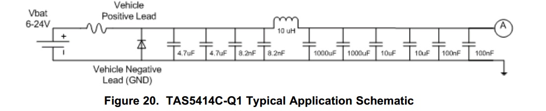
We are evaluating TAS5414C-Q1 for automotive infotainment system. Below is the power supply schematic from TAS5414C datasheet. Is it low pass pi filter (clc)? If, yes what is the cutoff frequency?

Is it to prevent alternator noise from creeping into the  audio signal? or to attenuate automotive power transients like load dump?

I have seen lot of reputed car stereos and amplifiers using 600uh -1 mh inductor and 3300uf capacitor forming low pass LC filter at power input to the system. This one is quite different. Any specific reason?

-M  

  • Hi, M,

    I believe you are looking at an old copy of the d/s - you should download the latest from our website.

    With that said, the configuration you indicated is indeed a filter component - since this device is a class-D amplifier, it draws pulses of power from the power supply, and this circuit is intended to block any RF noise from being injected back onto the power supply. This is necessary to meet OEM car manufacturers EMC requirements. Depending on your testing requirements, you may be able to eliminate this circuit.

    The diode, of course, prevents damage under reverse battery connection.

    -d2