This thread has been locked.

If you have a related question, please click the "Ask a related question" button in the top right corner. The newly created question will be automatically linked to this question.

How to measure the THD+N of TAS5706A

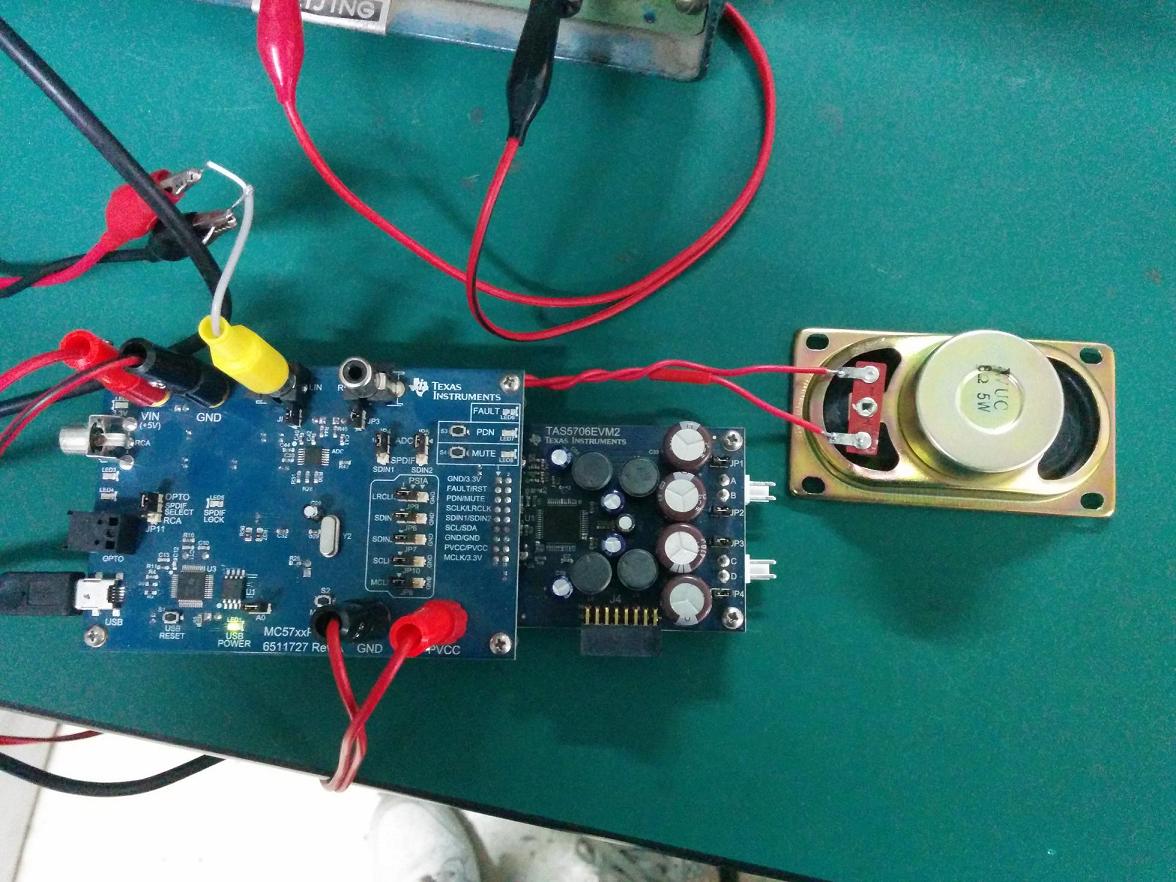
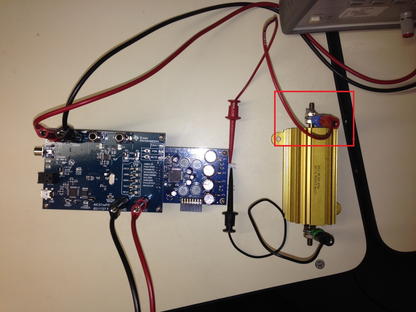
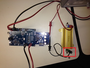
The measurement board isTAS5706EVM2 (with MC57xxPSIA). My  connection is the same as the following graph .Then the speaker(BD,BTL) is connected to A and B of interface .according to sloa068.pdf, two RC filters(100 ohm/47nf) is differently connected to pins of the speaker. but I found that  the value of THD +N(measured) is different from datasheet。

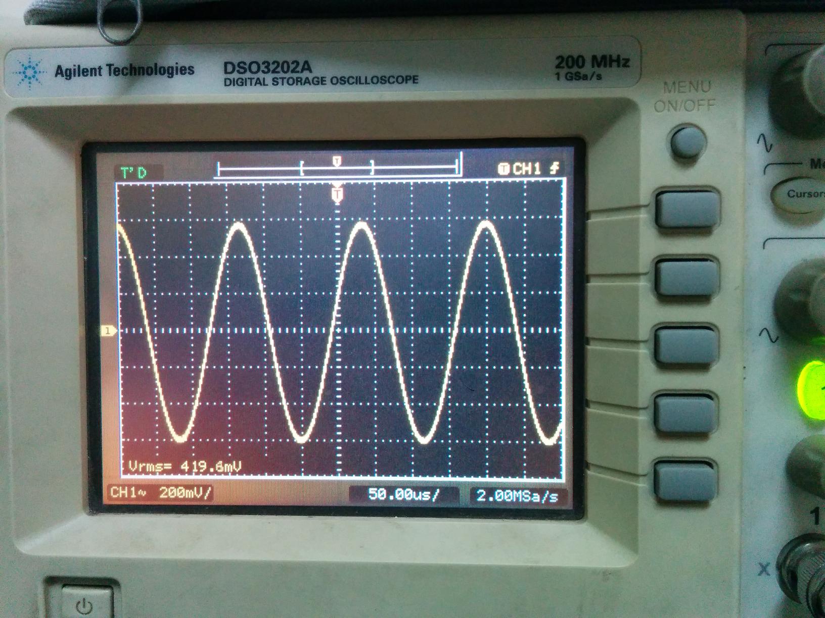
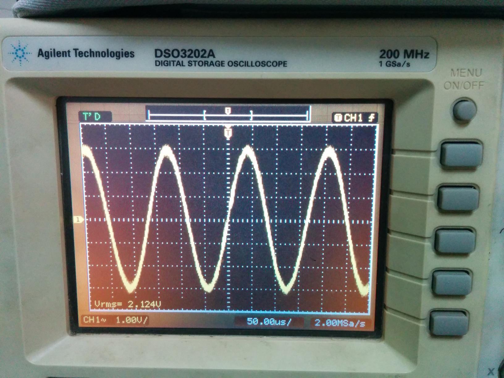
frequency(KHZ) power (W)  THD+N(%)
6                               0.66             4.7
6                               1                   3.9

How I measure the THD+N of TAS5706EVM2 ?Do you have a better solution?


  • Hello Jian,

    I'd be happy to look into this for you. A few quick follow up questions:

    What are you using to measure the thd?

    What voltage are you putting into the device? (PVCC)

    Could you tell me a little more about the load you are using? What is the resistance of the speaker?

    Could you include some oscilloscope screenshots of the input signal and output signal? This could be very useful to see what is causing the THD discrepancy.

    I look forward to the response,

    Nate


  • Hi,Nathaniel 

       1. The instrument that is used to measure THD is harmonic distortion analyzer(not  Audio Precision).It is Manufactured by factory of radio instrument of beijing (not existing)

    2. PVCC is18V.It is produced  by Transistor power.

    3. The resistance of the speaker(5W) is 8ohm.

    4.About oscilloscope screenshots of the input signal and output signal,I‘m sorry that I have come off work.But I can do it next monday.

  • Hmmm... yes for those settings your thd does seem quite high. I'll take a look at the screenshots on monday and if I can't determine the cause I'll see if I can recreate it in the lab and find out what could be going on.

    Thank you for the info!

    Nate

  • Hi,Nathaniel

      The following graphs are oscilloscope screenshots of the input signal and output signal.The parameters of the amplifier is configured as follows。By the way,The interfaces of C and D is not connected to speaker.

    frequency(KHZ)  Vin(mVrms) volume(dB) Vout(Vrms)

    6                         419.6                -12                   2.12

    graph 1. oscilloscope screenshot of the input signal

    graph 2. oscilloscope screenshot of the output signal

  • Jian,

    I'm actually hearing from another person about getting an inflated thd+n level with this EVM. I'll try to create the issue and see if I can find some possible solutions.

    Nate

  • Jian,

    I just set up the THD+N test using your same settings and got a thd+N of 0.15%. I used a single ended analog input, 18 V pvdd, 5 volts for VIn. .66 watts, and 6khz sine input to an 8 ohm load. I'm using the audio precision to measure the values. The values I got here line up with the results found in the datasheet.

    From this, I would suspect there is one of two reasons for seeing an increased THD+N:

    1) There is some error in the total harmonic distortion meter (you would have to refer to the manufacturer to see if it has any limitations of resolution or certain thresholds), or

    2) There is some setup issue that we are overlooking.

    One thing that stood out is how your speaker is connected to your evm. I'm not seeing it connect to the A and B jack near JP1 and JP2. How is your speaker attached to the output of the tas5706evm2?

    Nate

  • Hi,Nate

    From oscilloscope screenshot of the output signal,I think that it may be not problem of  harmonic distortion meter. I also suspect that there is some setup issue.Can you send the picture of measuring connection of TAS5706EVM2 to me?Also,please give me a quick-start setup of GUI and file of BTL .ini (tested).thanks a lot

  • Hello Jian,

    Here is a document I put together to describe the exact steps I took to run the test. It includes pictures of the setup along with screen shots of how I set up the GUI. 3324.How to measure THD+N TAS5706EVM.pdf

    I'm not familiar with the .ini file type you are looking for. Which program outputs the .ini?

    Hope this helps! Please let me know if you need anything else!

    Nate

  • Hi,Nate

    I have seen the document about measuring THD+N of the TAS5706EVM2.It seem to be similar with method provided by the document,besides AP.Unfortunately ,I could not own the analyzer and therefore not follow the document. Did you measure output signal of TAS5706EVM2 with oscilloscope ?Can you provide connection to measure output signal with a oscilloscope for you?

  • Hello Jian,

    When I run the tests, I usually do use an oscilloscope on the outputs (and inputs) to make sure all of the signals look correct. When connecting it to the TAS5706EVM2.

    When measuring the output I connect the scope probe to the positive side of the load.

    You will have to be careful with attaching the ground clip of the oscilliscope prob to the negative side of the load, as it's a differential output. So if you have another probe that is grounded it could short the negative signal.

    Did this answer your question? I'd like to confirm this is what you were asking.

    Nate

  • Hi,Nate

    I mean that distortion of output signal was large when I used a oscilliscope to measure output of TAS5706EVM.Did you experience it?How should I resolve it ?

  • Jian,

    The only time I got higher than expected distortion when using an oscilloscope was if I accidentally connected the ground of the voltage probe

    This :

    To the negative side of the load

    Here:

    If the ground of the probe is attached the the negative side of the load, and and the oscilloscope is grounded then it would short the negative terminal which would give a bad thd result.

    However, outside of that case, when the oscilloscope is attached during my testing it had no effect on THD+N.

    In terms of resolution, I don't have many more suggestions. I tested the EVM myself and found the distortion levels equal to what is found in the datasheet. If your setup is correct then the only thing that could cause this would be: 1) it's a bad EVM. Are you able to test another EVM and get the same result? 2) The test equipment is faulty. Is the power supply clean? Is the input signal good as well? It looked fine on the scope screen shot you sent, however, can you test the thd of the input signal?

    Does the sound coming out of the board sound distorted as well? 5%-10% thd could be audible.

    Nate