- Ask a related questionWhat is a related question?A related question is a question created from another question. When the related question is created, it will be automatically linked to the original question.
Hi,
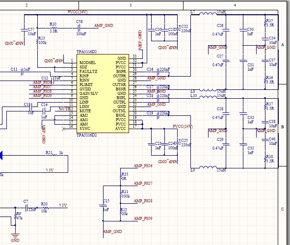
I am testing with the BT+3116+speaker module. I do test successfully with the BT module I built together with the EVM board and speaker part. Now I am trying to apply that on my self-designed PCB board. The only thing I changed now are the values of the LC filter part(from 680nF and 10uH to 15uH and 470nF), others all following the typical application on the 3116 datasheet. I got much noise now, which can hardly hear the music. Why do this kind of thing happen? I have two guesses:
1. The change of LC filter value
2. I placed wrong layout of inductor on the PCB board, so I am now using the wires for the connection.
Can anyone help me understand why the and where the noise come from?
Attached is the layout image.