This thread has been locked.

If you have a related question, please click the "Ask a related question" button in the top right corner. The newly created question will be automatically linked to this question.

TAS5717 Headphone and speaker output issue

Other Parts Discussed in Thread: TAS5717

Hi Team,

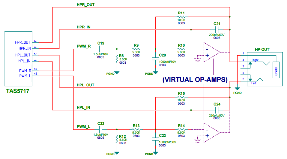
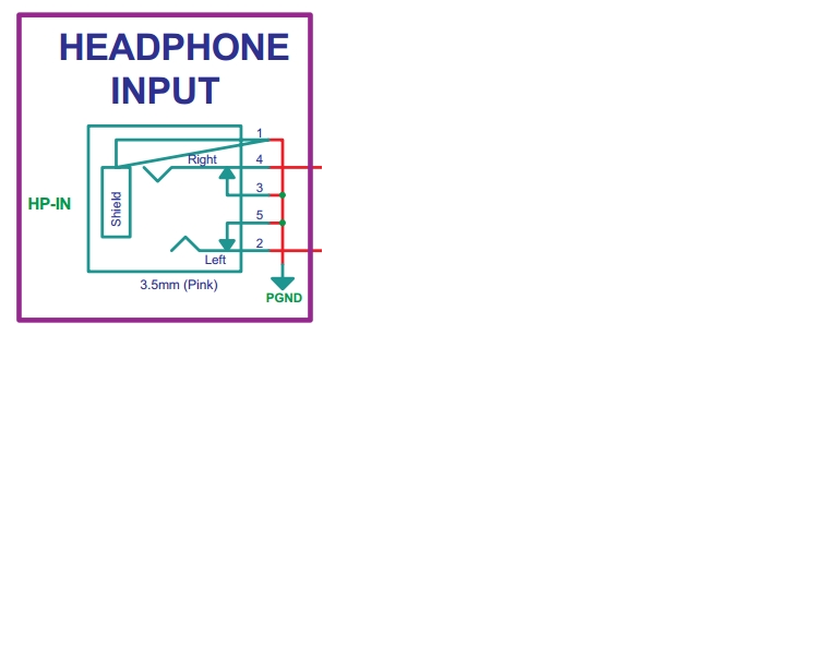
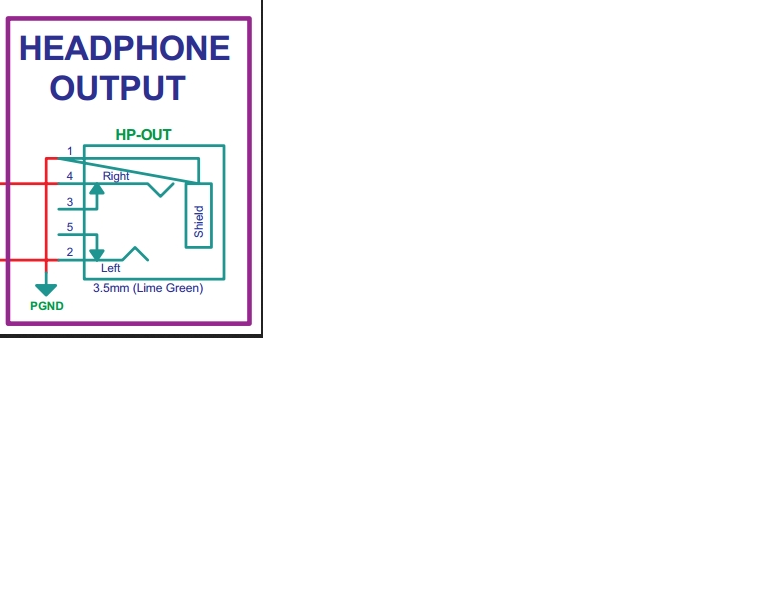
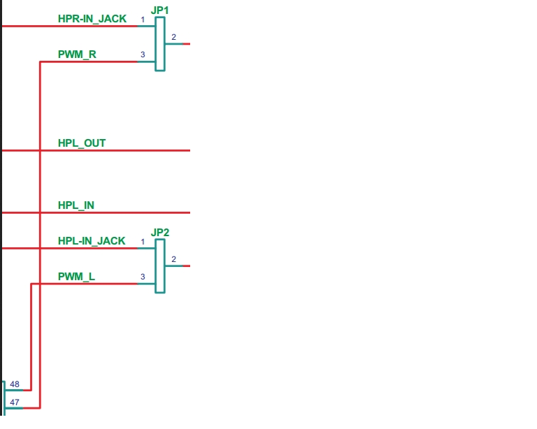
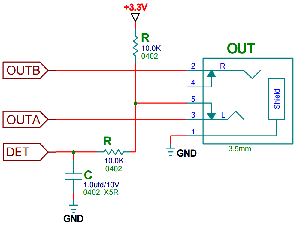
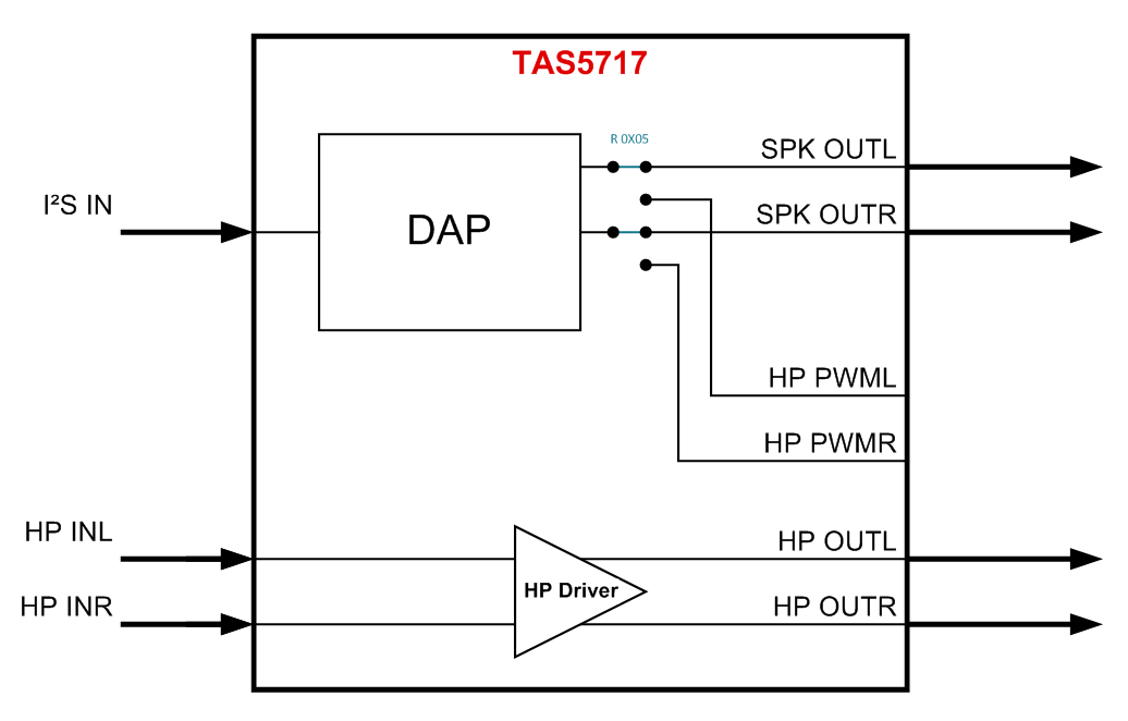
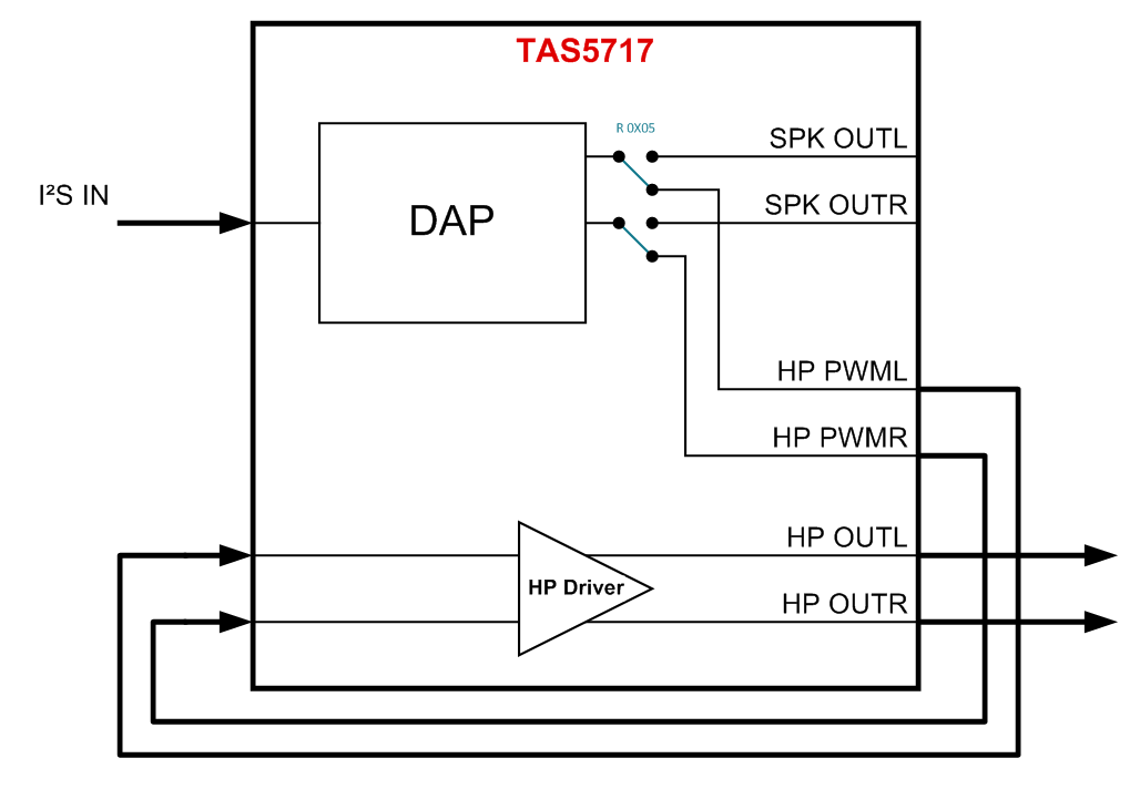
The customer is using TAS5717. The audio signal is input by I2S. He needs to achieved  this function.  The sound can be output from a 2*10W speaker when

the headphone is not inserted.  The sound can be output from the headphone  and the speaker can be mute when the headphone is inserted.

Can TAS5717 be achieved this function? If it can, how to set the register for TAS5717? And should the schematic be refered to the EVM schematic?

Thanks

Best Wishes,

Mickey Zhang

Asia Customer Support Center

Texas Instruments

  • Hi, Mickey,

    The TAS5717 can be used for this application. This amplifier is able to output a PWM signal from the digital audio processing block that can be used as the source for the Headphone/line driver (HP_PWMx). The speaker and PWM headphone outputs cannot be used at the same time as they both share the same digital audio channel. For information about how to configure properly the device for I²S HP output, please refer to page 56 of the datasheet.

    About the schematic, the EVM is designed to be flexible to evaluate the headphone driver with both analog and PWM input options, I am attaching a partial schematic that can be used as reference:

    Best Regards,

      -Diego Meléndez López
       Audio Applications Engineer

  • Hi Diego,
    Thank you for your support.

    Best Wishes,
    Mickey Zhang
    Asia Customer Support Center
    Texas Instruments
  • Hi Diegeo,
    The customer has other questions.

    Q1. The EVM schematic shows the HEADPHONE INPUT and HEADPHONE OUTPUT. For the  HEADPHONE INPUT, the 3pin and 5pin are connected to GND.

    But for the HEADPHONE OUTPUT, the 3pin and 5pin are floating. Can you explain the reason of  the 3pin and 5pin for the HEADPHONE INPUT and HEADPHONE OUTPUT?

    Q2. For the EVM schematic, JP1 is connected to HPR-IN_JACK and PWM_R. JP2  is connected to HPL-IN_JACK and PWM_L. 

    Can HPR-IN_JACK and PWM_R be connected together, not use JP1?

    Q3: The customer needs when it is the headphone output, the speaker should be mute. And when it is  the speaker  output, the headphone should be mute.

    How does TAS5717 complete this control? Is needed to add the headphone detection circuit?

    Q4: How does MCU control the switching from the headphone output to the speaker output or  from the speaker output to the  headphone output?  through HP_SD pin or the register 0x05? 

    Q5: If the input signal is the analog input, can the output be to the headphone and the speaker ? OR only to the headphone?

    Q6: Should the I2S pin be added the pull-down resistors?

  • Hi, Mickey,

    Please refer to the comments below:

    Q1: Pins 3 and 5 in the input are used to ground the inputs of the HP line when there is no plug connected in order to avoid noise issues. This is not required in the output, but can be used to detect if a plug has been inserted to the connector.

    Q2: HPx-IN is the analog input from the Headphone input connector, the jumper is used to select the source for the HP/Line driver of the TAS5717, between analog (HPx-IN) or PWM (from IC) inputs. Having both connected is not recommended.

    Q3: From the amplifier perspective, you can do this by changing register 0x05, but you need an external detection circuit to check whether a plug has been inserted to the HP output connector. When this happens, the system controller should mute the amplifier and configure it into Headphone mode. 

    Q4: This is done through software control, by changing register 0x05, but the HP/Line driver power control is made with HP_SD pin. 

    Q5: If analog input is used, the speaker output can work at the same time as headphone output. 

    Q6: I²S pins does not need a pull down resistor.

    Please let me know if you have more questions or comments.

    Best Regards,

      -Diego Meléndez López
       Audio Applications Engineer

  • Hi Diego,
    Thank you for your reply.
    For the Q3,
    (1) can you send me the external detection circuit schematic?
    (2) for "When this happens, the system controller should mute the amplifier and configure it into Headphone mode. ", what is the amplifier what you said? Is it TAS5717?  If the input is I2S, how does MCU control to mute the amplifier?

  • Hi, Mickey, 

    Please refer to below circuit. When the plug is disconnected, the logic value in DET is '0', when connected is '1'.

    Sorry for the confusion, the correct statement should be : "When this happens, the system controller should configure the amplifier to mute the speaker output and switch operation mode to Headphone mode."

    Best Regards,

      -Diego Meléndez López
       Audio Applications Engineer

  • Hi Diego,
    OK.
    If the input signal is only the analog signal input, that is the input signal is from HPL_IN and PR_IN, you mean the speaker and the headphone cant be output at the same time, right? Because the speaker channels are independent of headphone/line driver in this mode.

    If the input signal is only the I2S input, you mean the speaker and the headphone cant  not be output at the same time,right?

  • Hi, Mickey,

    When analog input is used for the Headphone Driver, Speaker output and headphone output can be used at the same time.

    When digital input is used for the Headphone Driver, Speaker output can't be used.

    Please let me know if you have further questions.

    Best Regards,

      -Diego Meléndez López
       Audio Applications Engineer

  • Hi Diego,
    Thank you for your assistance.