This thread has been locked.

If you have a related question, please click the "Ask a related question" button in the top right corner. The newly created question will be automatically linked to this question.

TPA3106D1: Input level for TPA3106, and VREG

Part Number: TPA3106D1

Hi:

I'm starting to design a guitar amplifier with TPA3106, and i have some questions about it.

First of all, what are the input signal levels that TPA3106 can work with... in the "Absolute max ratings" it says that INN and INP can be in the range of [-0.3V to VREG + 0.5V]. This means than i have to addapt my guitar signal with an input buffer to be as small as 0.3Vpp so it does not exceed the low limit?

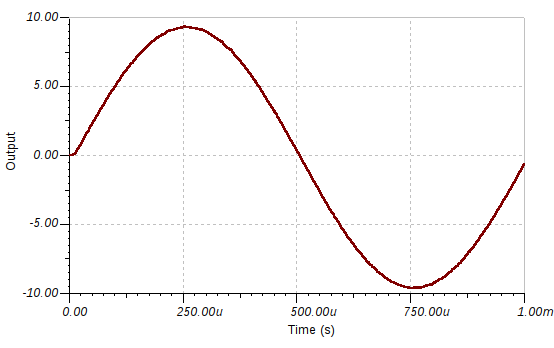
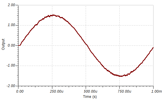
Another question is about VREG... in TINA reference design, it si connected to a 4V source... but in datasheet i understood that the 4V were regultated by the TPA3106 itself... and in the EVM schemtatics it is directly AC coupled to ground... why then in TINA reference design there is a DC source there? In the simulation, if i remove that source from the reference design, the output wave is visibly afected by some noise and the output level decreses a lot:

However, in the EVM schematics the 4V source to VREG is missing.

What should i do?

Thanks in advance for the help!

  • Hi Pablo,
    There are capacitor on the inputs, and the common voltage is around VREG/2 (~1.9V). So the maximum input which is accptable for input pins is Vp=1.9V, but please note that the output will be clipped and thermal protect probably will be caused in this case.
    The VREG terminal (pin 10) is the output of an internally generated 4-V supply, used for the oscillator, preamplifier, and gain control circuitry. It requires a 10-nF capacitor, placed close to the pin, to keep the regulator stable. It can be used to control GAIN0, GAIN1, MSTR/SLV, and MUTE terminals, but should not be used to drive external circuitry. Please follow our EVM SCH&PCB layout for your design.
    The simulation model is not a really part, it's just a virtual device to simulate the behavior. It can't be used for SCH design.
    Best regards,
    Shawn Zheng
  • Thanks a lot for your answer,

    I was using EVM SCH&PCB for design... but i was confused by the simulation schematic.

    I'm still a bit confused about the input range... I want to use a guitar with this amplifier, and i don't want my signal to be clipped... so how could i find the maximun input Vpp that i could use before output clipping? That way i could addapt my guitar output signal with a preamp...

    Thanks

  • Hi,
    I think i found out how to find maximun input...
    If i have max gain (36dB), and Vcc=24V, i can have 380mVp before the output reaches Vcc and, therefore, clips.. am i right?
  • Hi Pablo,

    Yes, your undestanding is correct.

    Best regards

    Shawn Zheng