This thread has been locked.

If you have a related question, please click the "Ask a related question" button in the top right corner. The newly created question will be automatically linked to this question.

TAS5715: TAS5715 - Trouble from chopped audio output to over-current draw

Part Number: TAS5715

Hello community,

I have an existing and hardly documented design in front of me that was used for a test circuit. It purpose was to modulate a LF signal onto a 40 kHz base band signal for ultrasonic emitters. Unfortunately we need to build up some more of this test circuits and now I have the challenge to make it work. PCBs are populated and while checking the function of the device I found out that the used TAS5715 IC is making some trouble.

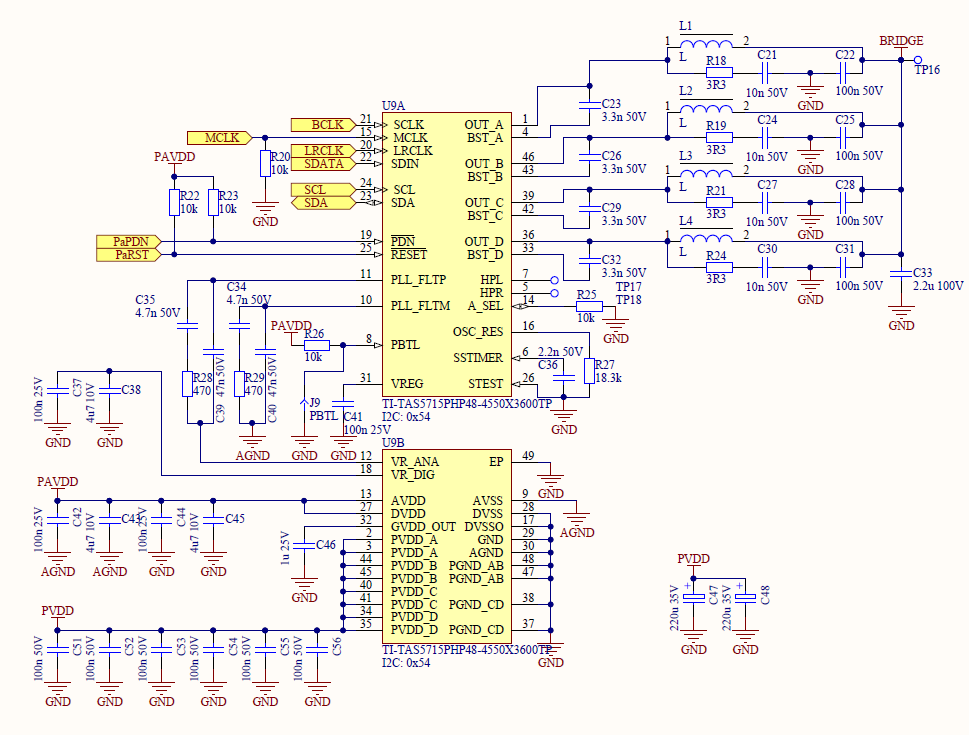
Here a picture of the schematic drawing. The inductors L1-L4 are populated with 15nH.

The signal "Bridge" goes to the 40kHz Amplifier and is connected for testing purpose to a small speaker via a DC decoupling capacitor of 10 nF.

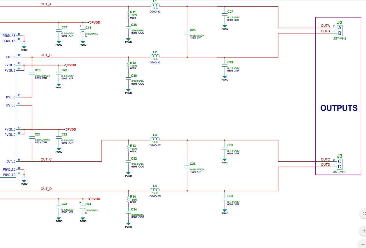
To give you a better picture I have also included the whole setup routing used for the TAS5715.

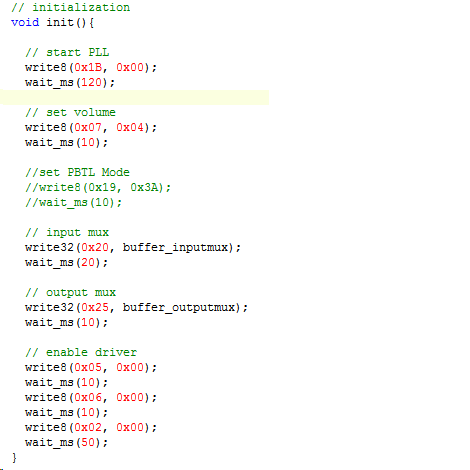
What I have observed so far. The sound of the TAS is chopped. Half a second sound the next half second cracking and creaking noises. Chip and Inductors are getting pretty warm, even in "Idle" mode without any sound signal on the I2S Pins. Current draw is about 330 mA for the TAS. From the datasheet I found a section that states to set register #19 to the value 0x3A while using PBTLE mode. This section is commented out in the setup routine. By enabling this register access the circuit is set to a non working mode where our power supply goes into over current protection. The I2S data is okay. Checked it with an additional amplifier in parallel. No trouble found for the I2S signal (48kHz, 256fs). Voltage supply's are also stable. The only thing that comes to my mind is the strange way used to establish the PBTL connection of the outputs. But I was told that the old circuits are working. So I hope that some of you have an idea to what I'm missing right now.

Best regards,

Christopher

  • Hmm I see that now the pictures are missing. Okay lets try again source code

    and schematic

  • Hello Christopher! Alex and Shawn can take a look at your question. But for clarification, is it your new circuit that is not working, or the original test circuit board that is not working? Thanks, Jeff
  • Hello Jeff,

    thank you for your reply, help is much appreciated. The new boards are the those, which are not working right now. Unfortunately I don't have access the old boards as reference. So all I could do, was to take the old project files, build up new boards and hope that they will work of the shelf. So far I have already corrected some placement errors on the rest of the board, checked the I2S signals with an simple amplifier module and tried to figure out if there is some mistake in the TAS5715 schematic drawing. But currently I'm lost.

    Best regards,

    Christopher

  • Hi Christopher,

    The TAS5715 device produces a differential output, so the problem I see is that the out+ and out- pins are being shorted together and the "bridge" output is referenced to ground.

    In BTL mode the device can drive 2 speakers (differential): chA = out1+, chB = out1-, chC = out2+, chD = out2-

    Below is an example of our evaluation board schematic configured in BTL mode:

    In PBTL mode it has a single output, which is also differential: chA=chB=out+ and chC=chD=out-. The heating up of the inductors and current draw of the IC also makes sense if the output is being shorted.

    If you can separate chAB and chCD the device should start working properly in PBTL mode. I would suggest trying that to check if this is the only problem with the system. Then you can work on getting the TAS5715 output to your amplifier. Can your 40kHz amplifier support a differential input?  

    Also the device has a current limit of 4.5A after which it will automatically shut off the output. It sounds like your power supply is limiting before this happens when the device is put into PBTL mode.

    Best,

    Alex

  • Hi Christopher,

    One more thought, what is the purpose of the 40kHz amplifier? The TAS5715 is an audio amplifier itself. It can drive speakers directly, and I imagine the ultrasound transmitters as well given these are not above the power limit of the device.

    Best,

    Alex
  • Hello Alex,

    thank you for taking your time to look over my problem. Before I start cutting PCB traces I would like to verify an additional point. I just figured out that I had not included the MUX register settings in my previous post. This is part of the original setup routine.

    From the datasheet I conclude that this way all 4 driver stages are set to be controlled via the same channel signal. While the default configuration is indeed a differential configuration, this configuration drives all channels in sync. Therefore there should be no problem with a short circuit over the driver stages. If I take a look at the PWM signals of the driver stages I can confirm this behavior.

    Output A to Output B

    Output A to Output C

    Output A to Output D

    All signals are synchronized while no "audio" signal is present.

    Yours faithfully,

    Christopher

  • Hello Forum,

    I've found the failure. The colleague who designed this circuit in the first place had a little trouble with powers of ten. The bootstrap capacitors where populated according to our BOM with 3.3 nF, while the datasheet states to use 33nF. After changing to 33nF capacitors as written in the fine manual, the TAS is now working properly.

  • Hi Christopher,

    Good catch! I had missed that decimal point as well when I reviewed the schematic you provided. If this solves your problem can I close this thread?

    Best,

    Alex

  • Hello Alex,

    yes this topic can be closed than.