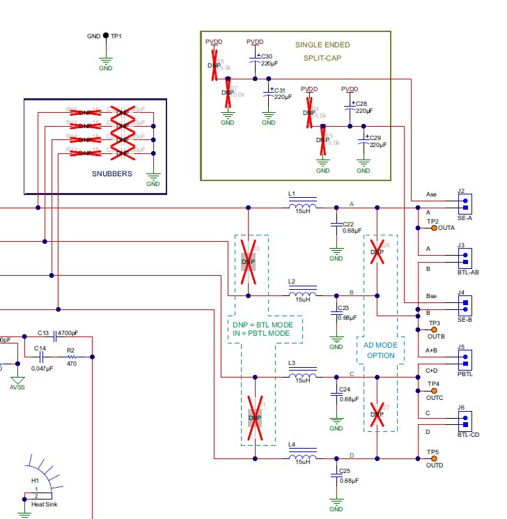
The TAS5755MEVM.pdf document shows the diagram below where the non-driven side of a single ended (SE) output has SINGLE-ENDED SPLIT-CAPs and/or do-not-populate resistors in a potential divider. This is confusing because the data sheet for the TAS5755M just shows the non-driven end of a SE speaker drive as connected to ground. I am designing a circuit for 2.1 where A & B are driving SE loads; please can you clarify what the recommended supporting circuit looks like?
Thanks.